I am working on a 5687 based gain stage for a dac. The dac is based on the tda1541a, uses a 33r resistor for the I/V, and is working fine. The tube circuit, however, is distorting quite a bit and gets worse with bass or loud notes.
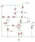
Schematic is attached -- there is a 4.7uF output cap attached between CLA1 and the output. The plate load CCS is at 10mA, cathode is biased up about 10V, B+ measures about 230V.
Does anyone have suggestions on where to look for what the problem might be?
-d
Schematic is attached -- there is a 4.7uF output cap attached between CLA1 and the output. The plate load CCS is at 10mA, cathode is biased up about 10V, B+ measures about 230V.
Does anyone have suggestions on where to look for what the problem might be?
-d
Attachments
A little more information. It seems that there is only a tiny bit of distortion when the amp first is turned on, but the longer it is on, the more distortion there is. The CCS transistors don't seem to be very hot and nothing appears odd -- i.e., there is no smoke.
I measured the current draw and it is pretty stable at 12mA -- slightly higher than I had intenbded, but not too bad either. The voltage is also stable, and otherwise things seem pretty quiet.
I measured the current draw and it is pretty stable at 12mA -- slightly higher than I had intenbded, but not too bad either. The voltage is also stable, and otherwise things seem pretty quiet.
Attachments
Hi,
I think you are looking for a cathode resistor in the range of 301 - 560 ohms. I run 5687 with these resistor values on 100V - 200V supplies.
I think if you look at the curves for the 5687 you are probably operating on the verge of cutoff for the plate voltage chosen. Bias like 3V or so would seem closer to the mark.
It's also possible that you don't have enough voltage across the CCS, but the CCS will fix the operating current, varying the cathode resistor will move you further up or down the curve for that plate current level. reduce your cathode resistance and the plate voltage will drop and therefore the voltage across the CCS will increase. This IMHO is why I don't like the CCS implementation, the operating point is now a complex interplay of tube and ccs behavior, linearity notwithstanding.
(I'm always fixing problems with this circuit topology for my various former experimenting clientele.. Over large tube sample sizes many of these circuits have no established norm for dc operating point. LOL)
Hope this helps
nuvistor said:What is the plate voltage?
Looking at the Tung-Sol 5687 datasheet characteristic curves, Vp=240V for Ip=12mA and Vgk=-12V. The active load may not have enough voltage across it, 10 to 20V drop should be OK. Perhaps a greater B+ or reducing the value of R3 would help.
B+ is high -- like 230V -- so I am actually dropping qiute a lot. Well, I think I am dropping quite a lot. Judging from the temperature of the transistors, I must not be dropping much at all. Maybe I;ll reduce one of the PS resistors to raise the voltage a few voltas and see what happens.
kevinkr said:Hi,
I think you are looking for a cathode resistor in the range of 301 - 560 ohms. I run 5687 with these resistor values on 100V - 200V supplies.
I think if you look at the curves for the 5687 you are probably operating on the verge of cutoff for the plate voltage chosen. Bias like 3V or so would seem closer to the mark.
I initially intended to use a 560R resistor, but accidentally ordered the wrong one and it does not fit the board. I'll see if I can't fix that somehow.
Thanks for the suggestions.
As kevinkr stated with some tube types there will be a large variation in plate voltage when using a CCS load. I use the 5842 and they vary so much that I needed to use a variable resistor in the cathode. I added this feature to the TubelabSE board (similar circuit). I don't find this much variation with the 12AT7.
I would try wiring a 1K pot in place of the cathode resistor (temporarily) and adjusting for best sound. Then measure the pot and substitute the closest available resistor. If your B+ is 230 then you want a plate voltage around 100 to 150 volts.
If you have more tubes, try a few and see if the plate voltage is different with each tube.
Well, I looked over the datasheet again, and I really just botched the math. It seems to have been a combination of the two problems. So, I used a 430R resistor for the cathode (the only reasonable thing I had around) and lowered B+ to about 200V and it seems to work quite well now. In fact, it sounds really spectacular -- I couldn't be more pleased.
That's a good suggestion -- the 1K pot -- that I should do for the next build. I think I don't need to leave quite as much room for the tube to swing as the input is only a fraction of a volt. As a preamp, though, it would need more.
Thanks
tubelab.com said:I would try wiring a 1K pot in place of the cathode resistor (temporarily) and adjusting for best sound. Then measure the pot and substitute the closest available resistor. If your B+ is 230 then you want a plate voltage around 100 to 150 volts.
If you have more tubes, try a few and see if the plate voltage is different with each tube.
That's a good suggestion -- the 1K pot -- that I should do for the next build. I think I don't need to leave quite as much room for the tube to swing as the input is only a fraction of a volt. As a preamp, though, it would need more.
Thanks
")
As an additional thought I would probably use fixed bias with a high transconductance triode like the 5842/471A or 5687 and CCS. That would make for a quick and easy setup and no pot or cap in the cathode circuit. Of course you would need a coupling cap at the grid and a bias setting pot, but at least it would not be in the signal path.
I use fixed bias in my headphone amplifier which uses a pair of 5842 in a white follower configuration per channel and have not experienced any significant drift with NOS Raytheon 5842 in two years of intermittent use.
I use fixed bias in my headphone amplifier which uses a pair of 5842 in a white follower configuration per channel and have not experienced any significant drift with NOS Raytheon 5842 in two years of intermittent use.
kevinkr said:As an additional thought I would probably use fixed bias
Can you post or point to a schematic? I can't keep the various terms straight.
I have built about 15 amplifiers with 2X 5842 in each all but one used military surplus Raytheon tubes. Each one has CCS load, and a well bypassed 1K pot in parallel with a 1 K resistor in the cathode. All of them have stayed put once they were initially set, but the pot settings were all over the place to get the right DC on the plate. I was setting them with an FFT analyzer, but this proved unecessary. Any plate voltage from 140 to 190 volts has the same harmonic spectra (320 volt supply).
The output tube bias is a different story. Each SE output transformer has an optimum current where it will deliver minimum 3rd harmonic. This is nearly independent of the output tube type. This seems true for triode mode. It doesn't hold for UL, and I haven't tested pentode connection.
The output tube bias is a different story. Each SE output transformer has an optimum current where it will deliver minimum 3rd harmonic. This is nearly independent of the output tube type. This seems true for triode mode. It doesn't hold for UL, and I haven't tested pentode connection.
arnoldc said:dsavitsk, sorry for the OT. but for fixed bias, you feed (-) voltage to the grid and ditch the cathode resistor so the cathode connects to ground.
So no cathode bypass cap? What are the best ways to bias the grid? Battery?
Hi, this is a circuit of joel tunnah which I got from his web site.
The 01As are fixed biased via a battery.
An externally hosted image should be here but it was not working when we last tested it.
The 01As are fixed biased via a battery.
- Status
- This old topic is closed. If you want to reopen this topic, contact a moderator using the "Report Post" button.
- Home
- Amplifiers
- Tubes / Valves
- Distorting 5687 preamp circuit