I would like to inform those who are interested in Dispre II PCBs, that they are still in production and available.
For more information please visit
Pavel Macura audiopage
Dispre II complementary-symmetrical preamplifier
Dispre II pricelist
For more information please visit
Pavel Macura audiopage
Dispre II complementary-symmetrical preamplifier
Dispre II pricelist
Hello Guys,
I am considering a possibility to design a new version of the Dispre 2 and PCB. Original thread is here:
http://www.diyaudio.com/forums/anal...reamp-successor-previous-popular-version.html
The new modification would have 2SK170/2SJ74 JFETs at the input. I would design a new PCB. In case you are interested in such modification, please write here or send me an e-mail.
Thanks,
PMA it is always nice to see your designs. I occasionally visit your site to see if you have new developments.
I think a Jfet input would be a rational and good development. (And perhaps you could consider a gain selection of x2.5 and x5, as I think this would cover the requirements of many people).
Also, I think there may be market interest if you developed a version with an output buffer to provide (Class A) 100 mW into 30 R (as a high quality headphone stage).
Regards,
G.
Well, I am interested to try that new version of the Dispre 2. ")
Not that I am not satisfied with the current iteration (V4). Au contraire!
I am really curious to know, having in mind the low cost of pcb and necessary parts that makes it a great bargain.
I would only suggest that this version provides more space that is necessary for larger value and better quality elcos (1000/35V or so as per current schematics).
Regards,
Baka
Last edited:
Gordy and Baka,
thank you for your inputs. I will carefully consider your recommendations. The PCB is under development and modifications are possible.
I expect to release one PCB design with same dimensions and geometry as the older BJT version had. I am asked by my customers to fulfill this requirement. Anyway, it would be possible to place the larger caps.
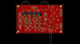
I am attaching the current status of the design (still under development).
Thanks,
thank you for your inputs. I will carefully consider your recommendations. The PCB is under development and modifications are possible.
I expect to release one PCB design with same dimensions and geometry as the older BJT version had. I am asked by my customers to fulfill this requirement. Anyway, it would be possible to place the larger caps.
I am attaching the current status of the design (still under development).
Thanks,
Attachments
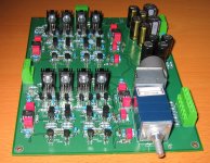
what will be the difference between you JFET DISPRE II a the jfet pre showed bellow
(take the note - only one output pairs sk/sj with idss 15-16mA
Please consider more space to use motorised pots
what will by the input capacitance of your jfet-dispre with input jfets pairs
(take the note - only one output pairs sk/sj with idss 15-16mA
Please consider more space to use motorised pots
what will by the input capacitance of your jfet-dispre with input jfets pairs
Attachments
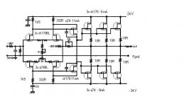
I was asked to modify this preamp
Dispre II complementary-symmetrical preamplifier
for JFET input. So, the resulting preamp would look like the original Dispre 2, with input stage replaced by self-bias JFET complementary-differential. And, the output diamond buffer would have resistors added to control and set idle current, to higher value than in the Dispre 2. Also, there would be a gain selector in the input.
The motorised pot would not be implemented now, but I can consider it as an optional next PCB.
Regards,
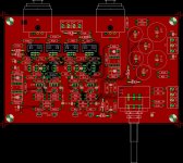
Is it possible to move the power supply section (input terminals and power supply caps) to the left side of pcb?
This way this section would be closer to power supply unit and power supply wires would not mess with input/output signal wires and volume pot (rod) on the right side.
Regards,
Baka
This way this section would be closer to power supply unit and power supply wires would not mess with input/output signal wires and volume pot (rod) on the right side.
Regards,
Baka
Hi Baka,
no, it is not possible, in order to keep continuity with previous BJT versions.
In fact, there is no problem with power supply mess, the background is extremely quiet, as documented in the record of -80dB signal:
http://web.telecom.cz/macura/snr.gif
This image is linked in the original Dispre 2 webpage.
Regards,
what kind of changes should be expected in the music reproduction with jfet input compl diff ?
The idss range of the used jfets ?
jfets on your pcb are quite far away from eachother , so it will be difficult to bond them thermally
There was some statement in one of Borbely articals , in case +12dB and more dual jfets should be used , but mayby that rule applies only to Borbely preamps
The idss range of the used jfets ?
jfets on your pcb are quite far away from eachother , so it will be difficult to bond them thermally
There was some statement in one of Borbely articals , in case +12dB and more dual jfets should be used , but mayby that rule applies only to Borbely preamps
I have some expectations regarding the resulting sound, based on listening comparison of Dispre 2 (BJT) vs. pre standard II (JFET). I will report after the evaluation sample is built, i.e. in a week or two. The PCB evaluation series will be produced on 17th May.
The voltage gain is achieved in the 2nd stage (VAS), and this VAS is with BC550/BC560. I do not expect necessity of thermal matching of input JFETs, based on experience with PA2 and PA4 amplifiers, which both have JFET input stages.
The voltage gain is achieved in the 2nd stage (VAS), and this VAS is with BC550/BC560. I do not expect necessity of thermal matching of input JFETs, based on experience with PA2 and PA4 amplifiers, which both have JFET input stages.
I would like to add some more info on Dispre 2 - JFET
Dispre 2 - JFET is a modification of Dispre 2 V4 preamplifier. The main difference is that Dispre 2 – JFET has Toshiba 2SK170/2SJ74 devices in the input stage, not the bipolar transistors that were used in the Dispre 2 V4. This modification resulted in a design of a new PCB board, as it was impossible to simply replace BJTs by JFETs, circuit modification of the input stage had to be made. At the same time, I added two resistors to enable setting of the output stage idle current.
Dispre 2 – JFET can be also used as a headphone amplifier, without any components changes needed.
Dispre 2 – JFET has complementary differential circuit topology with self biased JFET input stage (this topology was introduced by John Curl). This maximizes linearity of the input stage and distortion suppression does not rely only on an overall negative feedback.
Output stage idle current is set at 40mA, and it works in a class A up to 8V into 100 ohm load. For standard link load 600 ohm and higher, the output stage works in a class A for the whole range of output voltage up to clipping.
Dispre2 - JFET has wide bandwidth and high slew rate again, similarly as Dispre 2 V4.
Some of my customers required an option of overall gain reduction, not to use the potentiometer only at the beginning of its track. So I added two resistors, that enable to make a choice of overall gain from +1 to +5 (0dB to 14dB).
- Status
- This old topic is closed. If you want to reopen this topic, contact a moderator using the "Report Post" button.
- Home
- Vendor's Bazaar
- Dispre II PCBs available