Keantoken or perhaps Richard. I have read about paralleling some of these devices to lower the noise and other things by using mirrors and such and cascoding devices. What would happen if you took on of each of these devices you are just comparing and paralleled them in pairs, would this be possible or would one device be dominant over the other in a simple circuit. This is way over my head but I just had to ask.
If you parallel a BC3x7-40 with a BC5xxC, assuming the Vbe was close enough, I would say the noise of the BC5xxC would be halved because they both would have equal emitter impedance, so the BC3x7 would shunt the noise of the BC5xxC and the emitters would act like a voltage divider. It is an interesting idea, but I can't think of a way this would be an advantage over a different topology.
But I'm no expert on noise. I'll see what the simulator says about it.
But I'm no expert on noise. I'll see what the simulator says about it.
Last edited:
We have been paralleling bipolar transistors for about 45 years, and paralleling jfets is even more rewarding.
For example, the Levinson JC-1 pre-preamp introduced in 1973 used 8 complementary devices per channel to reduce the noise to approximately 0.4nV/rt Hz. This paralleling concept was first introduced (to me at least) by E.A. Faulkner in the mid 60's, in a British publication, 'Electronics Letters'.
The problem with paralleling is that you double current noise when you double the paralleled parts, so it is only really useful (with bipolars) for source impedances below 100 ohms.
A REALLY GOOD NOISE REFERENCE IS:
'The Design of Low-Noise Amplifiers' by Yishay Netzer
in the Proc. of IEEE, June 1981. This article will answer almost every question here, AND it is available for FREE from Google as a PDF. Unfortunately, it is too long for me to put it up directly, so those of you who are interested, you will have to push a few keys to get your copy. It is worth it.
Simulation confirms this, noise goes from 1.6nV/rtHz to 0.8nV/rtHz when a BC5xx is paralleled by a BC3x7. With two BC5xx in parallel it's 1.1nV/rtHz.
560 + 560 = noise 1.6nV gain 589
337 + 560 = noise 0.8nV gain 520
337 + 337 = noise 0.4nV gain 469
If one transistor has significantly worse flicker noise, this could help.
If one transistor has an Hfe of 100 and the other has an Hfe of 300 and they have equal currents, the Hfe of the combination will be 150, so maybe if you have several BC5xxC in parallel with one low-gain super low-noise transistor it could help?
There is a problem though in that the Vbe is mismatched. How would you fix the mismatch? One way would be a heat source to lower the Vbe of one transistor, if it wasn't too different. But I wonder if the benefits outweigh the cost?
Of course again, I have not really studied low-noise design so probably out of my depth here.
Simulation confirms this, noise goes from 1.6nV/rtHz to 0.8nV/rtHz when a BC5xx is paralleled by a BC3x7. With two BC5xx in parallel it's 1.1nV/rtHz.
560 + 560 = noise 1.6nV gain 589
337 + 560 = noise 0.8nV gain 520
337 + 337 = noise 0.4nV gain 469
If one transistor has significantly worse flicker noise, this could help.
If one transistor has an Hfe of 100 and the other has an Hfe of 300 and they have equal currents, the Hfe of the combination will be 150, so maybe if you have several BC5xxC in parallel with one low-gain super low-noise transistor it could help?

Gives more flexibility for different apps.
THx-RNMarsh
Another way to think about the noise impact of parallel devices, is to consider its effect upon base spreading resistance Rbb'.
Nine (Rbb' = 90 ohms) devices in parallel, gives a composite device with Rbb' = 10 ohms.
Homework problem: "N" number of BC327 transistors in parallel, gives the same Rbb' as a single 2SB737. Solve for "N". See posts 3159 and 3192 for possibly relevant data.
Nine (Rbb' = 90 ohms) devices in parallel, gives a composite device with Rbb' = 10 ohms.
Homework problem: "N" number of BC327 transistors in parallel, gives the same Rbb' as a single 2SB737. Solve for "N". See posts 3159 and 3192 for possibly relevant data.
Some of us still have practical applications for very low voltage noise.
With the right devices, it is possible to get within 1dB of http://www.hoffmann-hochfrequenz.de/downloads/lono.pdf with very simple circuits for a 5R source.
What do you use Iono for?
Do you mean me? "Joachim Gerhard" and "Gerhard" are different entities
I got bitten by an oscillator having unexpected phase noise peaks quite far off
the carrier and that could be traced to an exotic radiation hardened voltage regulator
for space applications, and I wanted an easy setup to check that.
Last week, I persuaded an Agilent 89441A to do 1Hz, 10Hz, 100Hz...1MHz FFTs
and combined those spectra to a single plot from 0.1 Hz to 1 MHz.
I think I'm ready to get get noise results from batteries, references and regulators
in a few working days now.
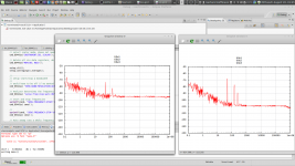
This is lono from 0.1Hz to 1 MHz. 15 dB below 1 nV/sqrt Hz outside 1/f.
(left trace noise of 60 Ohms=1nV/sqrtHz, right side = input shorted=amp voltage noise only.)
The 89441A can do cross correlation. That could bring another 25 dB or so, but requires 2 such preamplifiers.
regards, Gerhard
Attachments
Last edited:
We usually use ballast resistors, like 10 ohms in series with each emitter. 5 ohms would probably work OK.
Depending on Ic and Pd, you might not need any at all. BC3x7 are linear down to very low voltages so if you make Vce small you may not even need the resistors.
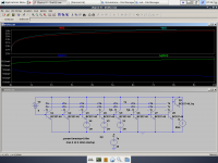
I made a thermal simulation to get an idea. Based on this you only get thermal instability beyond 20% if you violate Ic*Pd<860u for the TO92 package where the transistors are thermally coupled.
But I see no need to operate the BC3x7 at more than 1Vce so I don't think we actually need any ballast resistors at all.
Top traces are junction temperature, bottom traces are Ic for transistors 5 and 6.
Attachments
2: Almost nonexistant quasi-saturation - no better known transistor for low-Vce low-power applications such as C-multipliers, giving PSRR up to over 70db (the BC5xx follows closely at 60db, I wonder if newer BISS transistors from NXP could be better?). This also makes them ideal for current mirrors where gain is lost through quasisaturation (BIG mistake to use high-voltage japanese transistors here).
I guess this applies to both the NPN and PNP, as well as the SMD versions that use the same die - BC807/BC817. I'll give them a try in a current mirror shortly - I've used BC847C/857C in current mirrors earlier and they seem to work OK, but maybe the 807/817 are good substitutes with lower noise.
How did you measure the noise performance and what numbers did you get?Your work have inspired me to start measuring transistors in my parts bin. Found another decent performers, Zetex ZTX651/751.
1mA & 3mA would be good
My apologies Dr. HoffmannDo you mean me? "Joachim Gerhard" and "Gerhard" are different entities
Iono is indeed impressive.
If I still had a working turntable I would be tempted to ask to borrow it for some listening tests. I still have a couple of MC cartridges.
Do you mean me? "Joachim Gerhard" and "Gerhard" are different entities
I got bitten by an oscillator having unexpected phase noise peaks quite far off
the carrier and that could be traced to an exotic radiation hardened voltage regulator
for space applications, and I wanted an easy setup to check that.
Last week, I persuaded an Agilent 89441A to do 1Hz, 10Hz, 100Hz...1MHz FFTs
and combined those spectra to a single plot from 0.1 Hz to 1 MHz.
I think I'm ready to get get noise results from batteries, references and regulators
in a few working days now.
This is lono from 0.1Hz to 1 MHz. 15 dB below 1 nV/sqrt Hz outside 1/f.
(left trace noise of 60 Ohms=1nV/sqrtHz, right side = input shorted=amp voltage noise only.)
The 89441A can do cross correlation. That could bring another 25 dB or so, but requires 2 such preamplifiers.
regards, Gerhard
Hello Gerhard,
With this test system you are using to measure (I assume) the close in offset noise of the crystal oscillator, what are you using for the mixer a double balanced diode mixer. Did you make your own or is it an off the shelf part.
Regards
Arthur
We used an Agilent E5052B with cross correlation. My customer has the money for it.
The usual Mini Circuits ring mixers should do. I used TUF1-SM for similar applications.
SRA-1, SRA-3, probably SRA-3H are ok, too. Avoid extra high power mixers that have
resistors in the DC path to create bias. The resistors produce noise.
Someone from NIST claimed outstanding results for a ring mixer constructed from
2N2222 last year.
When you are at the point that the ring mixer makes a difference, you must already
have done a lot of things right.
The 89441A could be a low-cost way to precise phase noise measurement.
Last edited:
I think JC may use ballast resistors, not to prevent thermal runaway, but rather to provide negative feedback when the parallel devices have slightly different VBEon voltages. If (Rballast x Iemitter) >> delta_VBEon, the collector currents match very well.Depending on Ic and Pd, you might not need any [emitter ballast resistors] at all. BC3x7 are linear down to very low voltages so if you make Vce small you may not even need the resistors.
I made a thermal simulation to get an idea. Based on this you only get thermal instability beyond 20% if you violate Ic*Pd<860u for the TO92 package where the transistors are thermally coupled.
But I see no need to operate the BC3x7 at more than 1Vce so I don't think we actually need any ballast resistors at all.
D.Self refers to this as "series feedback" and suggests a rule-of-thumb for selecting Rballast.
JC, is this the noise paper ? :https://classes.yale.edu/04-05/enas627b/papers/lownoiseamp.pdf
In the Chris Trask test someone mentioned a dozen of pages ago,
it's funny that the 2N3866 is said to have bad large signal behaviour at > 50 mA,
yet it is constructed from lots of small transistors with lots of NiCr resistors in the emitters.
That paralleling-of-transistors game is much older than some people here would like to make us believe.
it's funny that the 2N3866 is said to have bad large signal behaviour at > 50 mA,
yet it is constructed from lots of small transistors with lots of NiCr resistors in the emitters.
That paralleling-of-transistors game is much older than some people here would like to make us believe.
- Home
- Source & Line
- Analog Line Level
- Discrete Opamp Open Design