@ John K. btw. ,
when i klick on your username to the left of your current/last posting #39 and then select
<View Public Profile>, then i am linked to the "user's-profile" of a user called
"krikor111", which seems wrong to me.
@DiyAudio: Is there something "messed up" in the datatase ?
?? And it takes me to "John K" which is not the same as "John K...". Something isn't right, for sure.
This is, what i get in #39:
"www.diyaudio.com/forums/members/john-k-.html"
And this is where i end up, when following that link:
diyAudio - View Profile: krikor111
Interesting ...
"www.diyaudio.com/forums/members/john-k-.html"
And this is where i end up, when following that link:
diyAudio - View Profile: krikor111
Interesting ...
Last edited:
Following my comments of post 39 I set up a simulation of a 8" midrange with 100 to 1500 Hz band pass. Then I added some side firing 5" drivers and LP filtered them to see what I could get. The simulation is limited but shows the idea. Note, I did not used any electronic (dsp) delays. The delay for the side firing drivers was introduced by the LP filter. Here are some simulation results.
This first figure shows, from left to right, top to bottom, the axial response of the 8" driver alone when used as a typical midrange. The figure directly below shows the separate response of the 8" driver and the summed 5" side drivers, on axis, when used to form a cardioid response. The boost at low frequency is required due to the gradient roll off of the cardioid. The figure at the top right is an over lay of the phase response, as seen from the rear, for the front and side drivers. Note that this is with all the drivers connected with the same polarity. This shows that at low frequency all drivers have the same phase response when observed from the rear of the system. Finally, the lower figure on the right shows the summed axial response of all the drivers (red) and the response from the rear of the system (blue) when the side drivers are connected with inverted polarity. The 100 - 1500 Hz band pass is the same as in the top left figure but from the rear significant reduction in output is observed.
The next figure shows the polar response of the system. The plots only show the front hemisphere but that is sufficient to observe the differences to be discussed. At the left the polar response of just the 8" driver is shown. Note that below about 800 Hz the response is omini-directional as indicated by the same SPL at all angles. Thus, there would be no attenuation at the rear. Above 800 Hz the driver directionality comes into play and the narrowing of the polar response is apparent. On the right the polar response is shown for the 3 driver system. Note the reduction in amplitude as the off axis angle increases. Also note that the polar response is basically constant from 100 to 1000 Hz and only narrows at 1500 Hz.
There are limitations to the simulation but I think this demonstrates the concept.
This first figure shows, from left to right, top to bottom, the axial response of the 8" driver alone when used as a typical midrange. The figure directly below shows the separate response of the 8" driver and the summed 5" side drivers, on axis, when used to form a cardioid response. The boost at low frequency is required due to the gradient roll off of the cardioid. The figure at the top right is an over lay of the phase response, as seen from the rear, for the front and side drivers. Note that this is with all the drivers connected with the same polarity. This shows that at low frequency all drivers have the same phase response when observed from the rear of the system. Finally, the lower figure on the right shows the summed axial response of all the drivers (red) and the response from the rear of the system (blue) when the side drivers are connected with inverted polarity. The 100 - 1500 Hz band pass is the same as in the top left figure but from the rear significant reduction in output is observed.
An externally hosted image should be here but it was not working when we last tested it.
The next figure shows the polar response of the system. The plots only show the front hemisphere but that is sufficient to observe the differences to be discussed. At the left the polar response of just the 8" driver is shown. Note that below about 800 Hz the response is omini-directional as indicated by the same SPL at all angles. Thus, there would be no attenuation at the rear. Above 800 Hz the driver directionality comes into play and the narrowing of the polar response is apparent. On the right the polar response is shown for the 3 driver system. Note the reduction in amplitude as the off axis angle increases. Also note that the polar response is basically constant from 100 to 1000 Hz and only narrows at 1500 Hz.
An externally hosted image should be here but it was not working when we last tested it.
There are limitations to the simulation but I think this demonstrates the concept.
Last edited:
Unfortunately shapes of LP filters for front and side woofers as well as strict relationship between LP corner frequencies of these drivers as well as relative distance between drivers are crucial in this method in order to form efficient cardioid response in given frequency range. Everything is linked. What is more drivers own directivity spoils the results higher in the midrange becouse of different radiating angles and baffle / diffraction issues.. Your sims show not that efficient directivity control due to mentioned issues. Big advantage of this approach is no forward cancellation between drivers array beacouse of filtering. It is worth a try. I will run some sims when I'll come back home later showing my results.
PS. Cancellation still occures but is filtered down in summed response with tweeter at the frequency where the tweeter takes control on system response. Steeper filtering than LR2 is advisable.
PS. Cancellation still occures but is filtered down in summed response with tweeter at the frequency where the tweeter takes control on system response. Steeper filtering than LR2 is advisable.
Last edited:
Unfortunately shapes of LP filters for front and side woofers as well as strict relationship between LP corner frequencies of these drivers as well as relative distance between drivers are crucial in this method in order to form efficient cardioid response. What is more drivers own directivity spoils the results higher in the midrange becouse of different radiating angles and baffle loss / diffraction issues.. Your sims show not that efficient directivity control due to mentioned issues. Big advantage of this approach is no forward cancellation between drivers array beacouse of filtering. It is worth a try. I will run some sims when I'll come back home later showing my results.
??? The syms include driver physical position, orientation and directionality.... . The modeled system could be built. Certainly a little tweaking would be necessary, but what new about that. It's just not that hard if you understand what going on.
Please show me rear hemisphere with consistent 20dB attenuation across mentioned passband in your sims to proove that.
Sorry, I can not do that as the sim code will not allow me to position the drives in a manner which would allow the polar plots to be made in the rear hemisphere. That's why I showed the comparison between front and rear axial plots and the phase at the rear. But since the sim code would be using the same data, if the polar plots could be mad they would show the same result at 180 degrees.
I would agree that in reality the rear null may not be as deep, but 10 or 15 dB attenuation at the lower frequencies would be easily achievable. It's a matter of building it and doing what is necessary to make it happen. Measure the amplitudes of the front and side drivers from the rear; Eq their responses to match as closely as reasonable and necessary, and get the phase right. I would prefer to implement this digitally, and using FIR filters, because it would be a lot simpler. And remember a 10dB attenuation is an order of magnitude reduction in intensity to the rear. I think a lot of people get carried away with the need for a deep null when it really doesn't accomplish much. 10 db reduces power by 90%. Another 10 db reduction would only reduce the power another 9%. Also, things are a lot less sensitive as you move away from 180 degrees.
This is something I did rather quickly to demonstrate the principle. I'll leave it to other to execute. In fact, I believe there have been some commercial speakers that that do just this. if you care to pick it apart, that's fine. It's noting more than a demonstration of principle.
Greatly thanks for explanation. 10dB is a lot of attenuation and certainly an achievement. I am astonished how efficiently it is implemented in commercial designs - 20dB of broadband attenuation is possible without DSP see Dutch&Dutch 8C it makes it passively with exceptional directivity consistence. and I was curious if you can model it more acurately than me. It is right move to eq the drivers identically and flip the phase in order to cancel it at given angle, but attenuation is valid only at this one spherical angle becouse of many real-life irregularities we cannot sim, which of them I mentioned. If you count them yes you can do -10dB or more at the 180 degree off-axis. Without real life optimization likely at say 135 degree there will be much less or even no attenuation in the same case. Cardioids are easy as long as wavelengths are long in comparison to diaphragm and box size. I am working exactly on this idea of LP filters difference-induced cardioid arrays. I am gathering funds for drivers, test boxes etc. In order to prove 'sims' that are legit.
P.S. I 'simmed' broadband second order directivity with LP minimum phase filters only involved (it is called shotgun I suppose) using only 3 drivers. DI of 9dB was no problem. Major problem was 12dB/oct loss of efficiency lower in frequency so it is no-go with nonlinear devices as dynamic loudspeakers are. 18dB of 3rd order harmonics amplification...
P.S. I 'simmed' broadband second order directivity with LP minimum phase filters only involved (it is called shotgun I suppose) using only 3 drivers. DI of 9dB was no problem. Major problem was 12dB/oct loss of efficiency lower in frequency so it is no-go with nonlinear devices as dynamic loudspeakers are. 18dB of 3rd order harmonics amplification...
Last edited:
Greatly thanks for explanation. 10dB is a lot of attenuation and certainly an achievement. I am astonished how efficiently it is implemented in commercial designs - 20dB of broadband attenuation is possible without DSP see Dutch&Dutch 8C it makes it passively with exceptional directivity consistence. and I was curious if you can model it more acurately than me...

An externally hosted image should be here but it was not working when we last tested it.
Yowza, that's some nice performance.
I haven't read the manual yet, but it LOOKS like Dutch & Dutch took the layout of the Kii audio Three and they simplified it? Basically they replaced the three driver DSP array and they replaced it with a single driver resistive cardioid?
So we have the following:
1) the high frequency directivity is controlled by a tweeter on a wave guide
2) the midrange directivity is controlled by a resistive cardioid
3) the low frequency directivity is controlled by an end fire array?
Since I'm obsessed with synergy horns, I see an obvious improvement here:
You could replace that front tweeter and midrange with a Synergy Horn. And then put the resistive ports on the sides, top, and bottom of the enclosure. By doing that, you'd get the same polar response on the vertical AND the horizontal axis.
Full range point source behavior that's symmetrical! That's a game changer, how great would it be?! Especially from such a small cabinet.
I haven't read the manual yet, but it LOOKS like Dutch & Dutch took the layout of the Kii audio Three and they simplified it? Basically they replaced the three driver DSP array and they replaced it with a single driver resistive cardioid?
So we have the following:
1) the high frequency directivity is controlled by a tweeter on a wave guide
2) the midrange directivity is controlled by a resistive cardioid
3) the low frequency directivity is controlled by an end fire array?
No it is simplier than you think! becouse there is no end-fire array here. Just sealed box with 100Hz LR4 xover to the resistive box. Special reflective arrangement inside bounces backwave to the side openings greatly enhancing its effectiveness in creating wideband cardioid extending from bass to the midrange. More dipole-like at the bottom, it blends nice with omnipolar sealed subs in order to form nice cardioid in midbass too. This is so clever monitor... I suppose it can play as well as Kii or even better giving the fact the polar response is created in natural (low DSP content) fashion.
I managed to "fool" the sim to get some polars at the rear overlaid with the front. Front polar plots for 200, 400 and 800 are all about the same.
With regard to the side venting, yes it works but it has some limits. The side vents act as side sources with inverted polarity, just as the 3 driver system does. Resistive loading of the vents acts as the LP filter on the on the back wave which introduces delay and high frequency attenuation. Basically, it's the same principle as the 3 driver approach but without independent control of the side response. I had experiments with something similar where I mounted a small driver on a circular baffle and used an automotive air filter as a circular vent with additional damping. That was many years ago when I was playing around with my ICTA design. I never completed that design because every time I got close the drivers I was using were discontinued by the manufacture.
If I actually designed something like this today I would use side mounted drivers with DSP and multichannel amplification. But, sorry, I have no interest in wasting time and money on another speaker design that ultimately won't make much of a difference in what my music sounds like. You can only chase your tail for so long.")
An externally hosted image should be here but it was not working when we last tested it.
With regard to the side venting, yes it works but it has some limits. The side vents act as side sources with inverted polarity, just as the 3 driver system does. Resistive loading of the vents acts as the LP filter on the on the back wave which introduces delay and high frequency attenuation. Basically, it's the same principle as the 3 driver approach but without independent control of the side response. I had experiments with something similar where I mounted a small driver on a circular baffle and used an automotive air filter as a circular vent with additional damping. That was many years ago when I was playing around with my ICTA design. I never completed that design because every time I got close the drivers I was using were discontinued by the manufacture.
If I actually designed something like this today I would use side mounted drivers with DSP and multichannel amplification. But, sorry, I have no interest in wasting time and money on another speaker design that ultimately won't make much of a difference in what my music sounds like. You can only chase your tail for so long.
More dipole-like at the bottom, it blends nice with omnipolar sealed subs in order to form nice cardioid in midbass too.
This I did with my old NaO Mini design: sealed sub with dipole mids and transition through x-o was dipole to cardioid to monopole. Also with a little speaker I called the Bird Cage.
"The design of the NaO Mini employing dual woofers (one woofer for each channel) uses a novel approach to accomplish this result for low frequency reproduction. Referring again to the Technical Studies area, and specifically to the technical article on Crossovers between different sources, it is apparent that when a monopole source (Mini woofer) is crossed over to a dipole source (Mini panel) using a 4th order acoustic crossover the polar response varies continuously from a dipole above the crossover, to a cardioid through the crossover region and then finally to a monopole response well below the crossover point. Since the crossover between the dipole panel and monopole woofer is centered in the sparsely modal region such a combination should result in a system which tends to minimize low frequency room interaction effects and sensitivity to placement."
From: NaO Mini Design Objectives
^That approach was also used in Gradient1.n series speakers in 1980's. I did it with minidsp utilizing ~160Hz/LR2 acoustic transition, because it gives wider range of cardioid and smoother transition zones - sounded better to my and friends' ears!
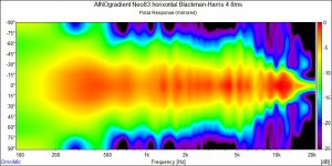
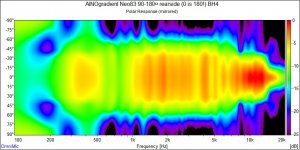
front and rearside horizontal polar measurements, indoors.
front and rearside horizontal polar measurements, indoors.
Attachments
@Windforce85: You DO realize the Dutch&Dutch 8C actually DOES use a DSP? Yes, the DSP isn't used for the cardioid but it is needed for the crossover, the variable lowcut, the equalization of the response. And it actually does have a wave guide, a short one but still a WG. So no, NONE of Patricks requirements have been met there.
@john: That are nice simulations. Soo clean. Yes, I still doubt they will measure like that.
@Patrick: Movies at night? Not disturbing the family? The lower mids aren't what they will be hearing, it's the bass. For a solution you could use the mentioned headphones, just disconnect the sub or simply use a body-shaker instead. If you've told what you're planning, 9/10 of the thread could just have been skipped.
I didn't tell you that no DSP is used in that system. There is DSP used that's why I wrote "low", it is different word than "no" DSP content.. The clue is that it is NOT used for cardioid here. Merit of this thread clearly shows that Patrick needs headphones. Rest is self-explanatory trial of doing something different and expression of our cardioid interest.
I have made two sims in Mapp XT:
It can model all diffraction and baffle issues in 360-degree angle span but is limited in filtering routnes as well as it sticks to the Meyer products only.
1: Classic loudspeaker

2: Three of these loudspeakers, two of them I rotated 90 degrees to the sides, and created acoustical offsets: 130 mm to the back, 100 mm to the sides from the front. -6dB attnuation of side firing loudspeakers is applied and finally, the phase inversion. Low-pass filters are set at 2kHz LR4 at the front, 600Hz LR4 on the sides:

Frequency responses are taken at the front and the back of this arrangement with two mics from 2 meters distance. As you can see, quite remarkable results from this simple method we can achieve. Up to 20 dB attenuation below 200-300Hz! No Equalisation and no further optimization is done in these "sims". It took me around 5 minutes to set this arrangement up for you. But these are only the sims.
It can model all diffraction and baffle issues in 360-degree angle span but is limited in filtering routnes as well as it sticks to the Meyer products only.
1: Classic loudspeaker
2: Three of these loudspeakers, two of them I rotated 90 degrees to the sides, and created acoustical offsets: 130 mm to the back, 100 mm to the sides from the front. -6dB attnuation of side firing loudspeakers is applied and finally, the phase inversion. Low-pass filters are set at 2kHz LR4 at the front, 600Hz LR4 on the sides:
Frequency responses are taken at the front and the back of this arrangement with two mics from 2 meters distance. As you can see, quite remarkable results from this simple method we can achieve. Up to 20 dB attenuation below 200-300Hz! No Equalisation and no further optimization is done in these "sims". It took me around 5 minutes to set this arrangement up for you. But these are only the sims.
- Status
- This old topic is closed. If you want to reopen this topic, contact a moderator using the "Report Post" button.
- Home
- Loudspeakers
- Multi-Way
- Directivity without Waveguides or DSP