Hi all
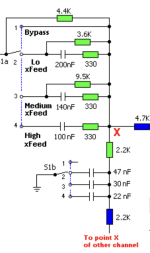
I started a little adventure: I‘ll try to make a little crossfeed „network“ according to Jan Meiers proposition… as this is a rather simple thing, I thought this could be ideal to try myself in smd.
But I‘m very unsure about what capacitors to use there? I mean, it’s caps in the very signal-path, which smd-caps are good/best to use <duck>soundwise</duck>
Thank you
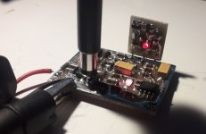
I got two of them, here's is the simple one and the other one (which is part of a whole HA..., here
I wonder if you conclude something other than pinholer's tip after reviewing the scm.
I wonder if you conclude something other than pinholer's tip after reviewing the scm.
Attachments
Try Panasonic ECHU( ECPU ) or Cornell Dubilier FCA series.I got two of them, here's is the simple one and the other one (which is part of a whole HA..., here
I wonder if you conclude something other than pinholer's tip after reviewing the scm.
COGs normally go up to 220nF at a normal price, there are also higher values but that is unnecessary for this application .
Attachments
Woops, I stand corrected...in my mind even pursuing values larger than 1nF was a no-no...but based mostly on price and suitability.
Myleftear, this application is pretty straight forward to build, and doesn't really need precision components, 5% - 10% tolerance in a decent quality cap will give good results.
Mike
Myleftear, this application is pretty straight forward to build, and doesn't really need precision components, 5% - 10% tolerance in a decent quality cap will give good results.
Mike
I have no trouble finding 1206 or 1210-sized ones rated for 50V or above up to 220 nF in stock at Mouser. They're not even super expensive. About $0.50/each at QTY 10.For that value range G0G/NP0 will be problematic, the largest values available generally no larger than 1nF.
C0G/NP0 tends to outperform film capacitors. Just make sure that you use physically large capacitors (1206 or larger preferred) rated for higher voltages (50+ V).
Tom
Polypropylene and polystyrene are not available in SMT as they melt before the solder does, PPS is the low distortion dielectric to use for SMT film caps.For that value range G0G/NP0 will be problematic, the largest values available generally no larger than 1nF. For quality audio, use a film cap, preferably polypropylene or polystyrene, although polyester (Mylar) is OK too.
Mike
If you're trying your hand at SMT -- I would suggest purchasing a stencil for your PCB designs. This makes the application of solder paste much quicker and more efficient. You can also invest in a hot-plate for melting the solder paste once the components are placed.
Once you get the knack, you might want to invest in a DIY reflow oven and a hot-air station for rework.
In addition to the C0G, there are acrylic and polyphenylene sulfide (PPS) film caps available.
I've compared SMT electrolytics with "through-hole" and the through-hole devices, in general, have lower ESR.
Why? What problems did you have? I've been using them for years and I solder them with a classic soldering iron, none of them are damaged and they all work flawlessly.Skip pps, they change value as soon as they see soldering iron coming close.
Attachments
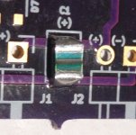
You've checked capacitance? They are EXTREMELY sensitive to direct heat. Best used with proper factory datasheet soldering procedure. For home made use and soldering, rubycon mu are hard to wreck. Easy 400C direct heat with no issues.
Edit: those on the picture look like acrylic (probably ecpu ones, same dielectric on rubycon mu, simmilar manufacturing), not pps. They handle a bit more heat than pps, but are still marked as reflow only in datasheet.
Edit: those on the picture look like acrylic (probably ecpu ones, same dielectric on rubycon mu, simmilar manufacturing), not pps. They handle a bit more heat than pps, but are still marked as reflow only in datasheet.
Last edited:
I seriously doubth you've left them unscathed in one manner or the other. Many people have had issues with much more experience (aya dacs with dem damaged caps what comes to mind). Even for some miracle they are virtually unharmed, recommending pps film cap to a novice in smd soldering is a recipe for disaster.
Here's a Yageo COG/NPO, rated at 0.1uF 50V
https://www.digikey.com/en/products/detail/yageo/CC1206JKNPO9BN104/9645658
https://www.digikey.com/en/products/detail/yageo/CC1206JKNPO9BN104/9645658
To follow up on the PPS stability issue.
Just got parts for another project and had a spare 12nF 2% PPS film cap, specifically ECH-U1C123GX5 from Mouser. So I measured the capacitance, then applied a soldering iron to one end for 3 seconds, let it cool and measured again. Then applied soldering iron to other end, let it cool and measured again:
before 12.14nF
1st end: 12.16nF
both: 12.16nF
So a change of 20pF out of 12000pF represents a 0.17% change due to temperature of soldering by hand. This is a 2% part so that is well within expectation. That soldering shift represents a shift of about 3% of a semitone, in musical terms...
Next time I have a spare part and a scrap PCB I can do the same test for oven-reflow.
- Home
- Design & Build
- Parts
- Dipping my toe in SMD-realms… parts recommendation (please?)