Hi LineArray,
Thanks for your insight. I'll do some experiements when there's chance.
Adding rumble signal to overcome the 'hysteresis' of the drivers is new to me. I didn't even think of that. Maybe it will work nicely. But there's a 80Hz HPF for your array, isn't it? Then the rumble would be largely attenuated. How do you plan on getting a good balance between over modulation and the effectiveness?
")
Thanks for your insight. I'll do some experiements when there's chance.
Adding rumble signal to overcome the 'hysteresis' of the drivers is new to me. I didn't even think of that. Maybe it will work nicely. But there's a 80Hz HPF for your array, isn't it? Then the rumble would be largely attenuated. How do you plan on getting a good balance between over modulation and the effectiveness?
I did not mean that "rumble" generator seriously
to 100% , but it was not just kidding too ... just
playing with options how to overcome a problem if
it cannot be solved at its roots.
In active speakers you could integrate such a
circuit even for all "highpassed" drivers, causing
a very small subsonic vibration, so the drivers have
always something to do ... even the tweeters.
Best would be to have drivers with little mechanical
loss and also amplifiers which work perfect for very
small signals.
There are some drivers on the market which have very
dominant damping by back-EMF and little mechanical loss.
On the other hand it is fairly impossible to make good
drivers without some amount of mechanical damping
in the membrane and the surround, because you need
it to control vibrational modes.
So it is kind of a typical deal with different tradeoffs.
But i feel mostly dome tweeters with heavily impregnated
surround suffer from that nonlinearities at low excursion.
Some (pure) ribbon tweeters may be good in that respect,
as they get a large amount of damping from radiation and
air friction, so usually those need no dampening coat.
In dipol 08 i only made that observations mentioned
with the tweeters, but i would say it is a very minor
issue.
Dome tweeters with heavily impregnated surround and/or
ferrofluid in the magnetic gap are candidates which
should be inspected for distorsion at low excursion
and shift of parameters depending on signal level ...
This is why i no not use ferrofluid tweeters.
Best
Last edited:
Hi LineArray,
...
How do you plan on getting a good balance between over modulation and the effectiveness?
...
If such a circuit could be shown to have a "healing"
influence you would do it like with any compensational
measure ... measure low level distorsion and increase
the "residual rumble" until there's no improvement
to be detected ?
Signal could be bandwitdh limited noise, maybe a
5-15 Hz sine would even do for prototypical
experimenting ...
FR 125 S Datasheet
This datasheet refers to FR 125 S, the new version
FR 125 SR does not differ significantly, but has
a changed basket design with identical dimensions
for mounting.
This datasheet is somewhat more detailed than the
single page version mostly found in the net.
FR data is rather smoothed, like usually in manufacturers
datasheets ...
http://www.meniscusaudio.com/images/CSS-FR125-data-v3s.pdf
Last edited:
These are the tweeters used (2 tweeters per panel):
Monacor DT 25 N
DT-25N - Monacor Neodymium HiFi tweeter 80Wmax 8Ω - Europe Audio
DT-25N Neodymium-HiFi-Hochtöner, 80Wmax, 8Ohm MONACOR / IMG Stage Line günstig kaufen schnell bestellen
A comparable one may be
Audax TM 025 F17
But the tweeter panel's crossover would have to be
changed for this one ...
(lower Re, higher voltage sensitivity)
Last edited:
Hello Oliver,
Nice project!
Let me ask some questions to understand the design more:
1) How and where the tweeter panels are placed with the main panels? Got any picture with the tweeter panels installed?
2) How high the 6 fulrangers play with the cross over? I see a treble boost. Does it mean there play the top range as well?
3) Have any measured acoustical responses of the lower and upper triples separately with the cross over?
4) And the tweeter measured responses with the cross over?
The long list of questions indicates I may have missed the essentials of your design
- Elias
Hello Elias,
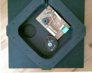
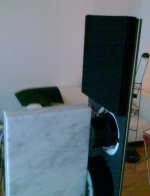
1) Maybe the attached picture helps ...
2) Yes ... the tweeter panel is only for correction
of the polar response to the rear.
Under free space conditions or in very absorbent
rooms the contribution of the tweeter panel is
less important. In usual living rooms it is
advantageous ...
The upper trio of fullrangers gets dominant above
4Khz, as you can see from the voltage transfer
curve of the filter i have posted.
3) I have no "isolated" responses - in fact there is
no such thing as the lower trio of fullrangers
is in connected in series with the upper trio
... maybe have a look at the wiring diagram
i posted in the beginning.
There is a simulation of upper 3 vs. all 6 drivers, at
http://www.dipol-audio.de/dipol08_simulationen.html
but with idealized drivers and without "treble boost".
4) Same as 3) but i may find a diagram of
the voltage transfer function for the tweeters ...
Kind Regards
Attachments
Last edited:
Thanks it's more clear now.
How did you end up with the driver spacings, is there a formula or is it based on iteration of vector summation with simulator?
Using such a sparse arrray it is all against the common gospel of center to center spacing and all that
However I don't doubt its functionality.
This is quite interesting. I took another look at the voltage transfer functions and it seems upper and lower triples are identical up to 3kHz. The 3dB difference point seems to be at 7kHz. At first it sounds a bit high, but then the fullrangers are starting to beam and it might lessen the comb filtering.
What happens if you move vertically from the floor level up to the top of the array, where is the perceived point of radiation? Does it follow you as you move or is it fixed spot withing the array i.e. is there a tilt in the wave front? Let's say the distance to the array is about 2m.
- Elias
How did you end up with the driver spacings, is there a formula or is it based on iteration of vector summation with simulator?
Using such a sparse arrray it is all against the common gospel of center to center spacing and all that
However I don't doubt its functionality.
.
The frequency dependent voltage shift between the
driver groups is very smooth, so you cannot really
detect which fullranger reproduces which frequency
range from usual listening positions, the array sounds
as being centered subjectively around the 2nd driver
from above as a consequence of the combined effects
of distance weighting and power tapering.
This is quite interesting. I took another look at the voltage transfer functions and it seems upper and lower triples are identical up to 3kHz. The 3dB difference point seems to be at 7kHz. At first it sounds a bit high, but then the fullrangers are starting to beam and it might lessen the comb filtering.
What happens if you move vertically from the floor level up to the top of the array, where is the perceived point of radiation? Does it follow you as you move or is it fixed spot withing the array i.e. is there a tilt in the wave front? Let's say the distance to the array is about 2m.
- Elias
Thanks it's more clear now.
How did you end up with the driver spacings, is there a formula or is it based on iteration of vector summation with simulator?
...
Iteration with simulator starting with an equidistant
array as a base .... golomb rulers were the
initial inspiration for modifying the spacing ...
...
Using such a sparse arrray it is all against the common gospel of center to center spacing and all that
...
Yes, the speaker breaks all the rules in the book.
But it is a kind of "bending" the rules, not just
ignoring them. As the orthodox close CTC spaced line
array rules cannot be obeyed using mid sized
fullrangers anyway, no matter how close you mount
them ... a point which often overlooked i feel.
...
What happens if you move vertically from the floor level up to the top of the array, where is the perceived point of radiation? Does it follow you as you move or is it fixed spot withing the array i.e. is there a tilt in the wave front? Let's say the distance to the array is about 2m.
...
It does not follow in the way a long vertical ribbon
line source follows your ears when "knee bending".
At a distance of 2m you feel some "soft centering"
around the upper drivers, resembling presence
and brillance coming from there and the sound
sources being more dense - it is always the combined
filter + spacing effect which makes up the subjective
centering.
Many people have been "knee bending" in front of this
speakers - you do not experience "gaps" or discontinuities
although those are there, but the spectrum wiggles smoothly
dependent on vertical angle - balanced enough
to statisfy even experienced listeners.
Compared to other speakers they are "statistically
balanced", no extremes occur at certain angles.
If you listen too close and sit on a low sofa there is
a tendency of slightly missing sparkle - but at listening
distances from 1,5m on sitting and standing gives the
same subjective balance.
The comb filtering is much influenced and mitigated
by the non equidistant spacing ...
Kind Regards
Last edited:
Hello,
The Golomb ruler seems interesting.
Now I'm thinking about Bessel arrays. They should be not too far from your ("statistic") array in a conseptual sense. Did you simulate a Bessel array for a comparison?
I simulated Bessels in several occasions in the past, but I never build one yet. Simulations showed quite good and uniform performance. However, the main blockage for me not to build one is that from an array I want the maximum directivity possible! Thus I use a straigh line array, no tapering of any kind. If I want less directivity I decided to use some other consepts.
- Elias
Iteration with simulator starting with an equidistant
array as a base .... golomb rulers were the
initial inspiration for modifying the spacing ...
...
Compared to other speakers they are "statistically
balanced", no extremes occur at certain angles.
...
Kind Regards
Hello Elias,
i kind of agree with your estimation that bessel arrays
have something in common ...
I attended a demonstration of a bessel array in
different configurations - not only line array -
at a local university here and had some exchange
of experience with the designer too some years ago.
Dipol 08 is more directional in the vertical
plane than a 5 or 7 driver bessel array would be ...
---
In a dipole line array using a frequency independent
voltage distribution according to a bessel function,
would not allow for the same lower frequency limit
and dynamic headroom in the bass, if you were to
use the same drivers ...
In a dipole line array you have to make the best of the
mechanical limits of your drivers, which implies to have
the same excursion for all drivers in the bass and make
use of the total amount of volume displacement possible.
Also think of distorsion ... a chain is as strong as it's
weakest link, or the most burdened driver(s).
Driver load in dipol 08 is equal in the bass for all drivers.
I can rely on that smallish drivers only because
the FR 125 S driver has large excursion and a special
motor, which makes the driving force nearly as constant
within sane excursion limits as if it would be an
underhung voice coil design, it is a double magnetic
gap design in fact.
You can forget that design using equally small
Fostex drivers e.g. ...
Dipol 08 is designed to work in combination with a
monophonic subwoofer - if necessary - and be able
to "standalone" above 80-100 Hz, giving a smooth
overlap with the woofer.
Using a bessel array you will need more or larger drivers
or you have to go up significantly with the crossover
frequency.
In that case you will need stereo subwoofers, which
have to be placed somewhere near(er) to the arrays.
Using a wider baffle would be possible also to increase
the dipole path length and reduce excursion, but then you
have to consider side lobing of the array.
Having all that in mind, the dipol 08 design is very
conciously chosen ... and driven to the edge of sane
mechanical limits using small drivers and a narrow baffle.
The subwoofer covers the range which is typically
affected by room gain (<80 Hz) and can be placed
for optimum balanced mode excitation in a fairly
wide area ... adjusting its level accounts for specific
room gain rather well, so the system is easy to adjust
for different rooms:
- Place the satellites for best stereo imaging
- Place the subwoofer for balanced low frequency
mode excitation rather independently
- Fine adjust subwoofer level properly for seamless
integration according to room specific gain.
Ready.
Ready means: No fumbling with the crossover frequency,
no fumbling with the slopes of the satellites.
Kind Regards
Last edited:
hello oliver,
i'm very interested in your design. how do you think the principle will work using smaller driver Vifa Breitbandlautsprecher 9 BN 119/8 and crossed higher (200-300hz) to stereo dipole subs?
thanks
martin
i'm very interested in your design. how do you think the principle will work using smaller driver Vifa Breitbandlautsprecher 9 BN 119/8 and crossed higher (200-300hz) to stereo dipole subs?
thanks
martin
Hello Martin,
using stereo subs is obligatory then, yes.
The principle will work, but you will have to re-
align all the crossover stuff and also the baffle
dimensions (width about 2 .. 2.2 X cone diameter etc.)
Maybe you can also shrink the height a bit.
One interesting feature in 'Dipol 08' is having noticeable
vertical directivity in the transition region of the room.
You may loose that a bit, but especially when using dipole
subs i would say 'yes it can work if implemented carefully'.
Kind Regards
Last edited:
Hi Martin,
yes transition region means the frequency range
where the room goes from modal (resonant) bahaviour
to statistical (reverberant) behaviour.
That is the range around Schroeder frequency (and
often above). Fs is often around 120Hz dependent
on the room's size and furniture.
But many roms lack diffusivity even up to the lower
midrange.
For gross simulation of the baffle diffraction you can
use e.g. EDGE from Tolvan Data.
But this won't help you aligning the drivers "correction
network" since that software uses idealized drivers.
You will need some experience and measurement tools
to make a new version work.
E.g. exact knowledge of the driver's voice coil inductance
will help in simulating passive crossover/equalisation
networks using appropriate software.
So in my view it will lead into a
simulation/measurement/listening test
cycle to refine your system ...
You can start using a test baffle without eq network, all
the drivers in series-parallel circuit to aquire first data and
listening impression. But that will be just the start of your
journey.
Kind Regards
Last edited:
thanks Oliver!
measurement and crossovers are no problem for me (I use digital filtering, so I'm sure I can fine-tune easily)
I should have said - what kind of simulation did you use to find the driver layout on the baffle - to minimize comb filtering? is edge useful here?
anyway, if I decide to try your design I will post results. thanks for your support!
martin
...
I should have said - what kind of simulation did you use to find the driver layout on the baffle - to minimize comb filtering? is edge useful here?
...
martin
Of course, EDGE is useful here. For low frequency behaviour you may use
it in a 'creative' manner and simulate also the bottom reflections from the
line array by mirroring the baffle at the "bottom line".
For LF behaviour that mirrored configuration using all drivers may serve
as a starting point, while for HF the upper 3 drivers are more in the focus.
Unfortunately you cannot simulate crossing over or drivers having different
input voltages in EDGE AFAIK.
To make the bottom-mirrored baffle (double height) fit into the sketch
window of EDGE you can turn it by 90 degrees ....
So you are just turning the space and moving the virtual mic up and down
on the screen resembles moving it sideways "in reality" ...
Because of said drawbacks i would not call it "simulation", but used
wisely and "with a grain of salt" it will yield some orientation in design.
You cannot simulate the cone breakup either ... so it might be usefull to
"do as if" the cones would be somewhat smaller at HF.
But that should not affect "good distances/ratios" that much, you will find
out quickly that some "rulers" will work rather "well behaved" at likely
listening positions while others will not.
It is also beneficial to look at larger (even vertical) off axis angles
(yes, where is the "axis", you have to define your own in a practical way
.. use a certain height or "2nd driver from above", which makes
intermediate results more comparable IMO)
...
if I decide to try your design I will post results.
...
martin
Sure ... looking forward.
Kind Regards
Last edited:
- Status
- This old topic is closed. If you want to reopen this topic, contact a moderator using the "Report Post" button.
- Home
- Loudspeakers
- Full Range
- "Dipol 08" Baffle Dimension and List of Crossover Parts