"Dear Dennis,
I will be very honest inasmuch as I just don't have the time at the moment to
write tutorials on amplifier design. However, trust me when I tell you that
the late great Sid Smith was a genius. The use of the Power Diodes in the
output stage of the Marantz Model 15 (of which I was the final engineer on)
had a very necessary purpose. In the Ampzilla (and first in the SAE Mark
IIIC) I used Shottky power diodes, NOT normal power rectifiers like in the
15, but for a completely different purpose. JB"
I think that the Schottky diodes in the Ampzilla were to limit dissipation in the large value emitter resisors (probably chosen for bias stability), and to reduce the voltage loss. JB never gives any technical info to a question, and snubs people in person when asked a question.
"Dear Dennis,
I will be very honest inasmuch as I just don't have the time at the moment to
write tutorials on amplifier design. However, trust me when I tell you that
the late great Sid Smith was a genius. The use of the Power Diodes in the
output stage of the Marantz Model 15 (of which I was the final engineer on)
had a very necessary purpose. In the Ampzilla (and first in the SAE Mark
IIIC) I used Shottky power diodes, NOT normal power rectifiers like in the
15, but for a completely different purpose. JB"
I think that the Schottky diodes in the Ampzilla were to limit dissipation in the large value emitter resisors (probably chosen for bias stability), and to reduce the voltage loss. JB never gives any technical info to a question, and snubs people in person when asked a question.
James B. actually did as I posted before. I will scan a page or two...
This is from his white paper modestly called The Ultimate Amplifier.
")
Attachments
Incidentally the tiny multi-diode packs often used for base bias setting in amps of this vintage were notorious for going intermittent o/c, or having varying volts drop. If an amp was overheating or had blown up for no apparent reason, I tended to replace them with a handwired, conventional Vbe multiplier.
Even if an official repair kit had one of these multidiodes, I would throw it away and fit a Vbe multiplier. Very rarely saw any such mods back in the shop, but plenty multidiode-equipped amps came back again for a repeat output-stage rebuild. With, of course, an irate owner spitting fury.
Even if an official repair kit had one of these multidiodes, I would throw it away and fit a Vbe multiplier. Very rarely saw any such mods back in the shop, but plenty multidiode-equipped amps came back again for a repeat output-stage rebuild. With, of course, an irate owner spitting fury.
I don't use microcap unfortunately, I'm on LTspice.
It's just a basic generic darlington emitter follower output stage if you want to try it in LT spice. Single 1K resistor between the emitters of the drivers, biased to about 200mA and running from 30V rails.
"Dear Dennis,
I will be very honest inasmuch as I just don't have the time at the moment to
write tutorials on amplifier design. However, trust me when I tell you that
the late great Sid Smith was a genius. The use of the Power Diodes in the
output stage of the Marantz Model 15 (of which I was the final engineer on)
had a very necessary purpose. In the Ampzilla (and first in the SAE Mark
IIIC) I used Shottky power diodes, NOT normal power rectifiers like in the
15, but for a completely different purpose. JB"
I think that the Schottky diodes in the Ampzilla were to limit dissipation in the large value emitter resisors (probably chosen for bias stability), and to reduce the voltage loss. JB never gives any technical info to a question, and snubs people in person when asked a question.
JB seems to contradict himself here... if you read the letter from Electronics World he there claims that the diodes are to reduce crossover distortion. No mention of dissipation in emitter resistors..
QSerraTico_Tico. Any possibility of the rest of that white paper?
the diodes are to reduce crossover distortion. No mention of dissipation in emitter resistors..
Hard to understand how they could reduce x-over distortion, since the voltage across a low-value resistor would be far less than diode turn-on at the x-over point.
More plausibly, I wonder if they used high-value emitter resisitors to combat poor quiescent current stability (for reasons mentioned previously) and then realized that the resistors couldn't carry the max current.
Last edited:
Hard to understand how they could reduce x-over distortion, since the voltage across a low-value resistor would be far less than diode turn-on at the x-over point.
More plausibly, I wonder if they used high-value emitter resisitors to combat poor quiescent current stability (for reasons mentioned previously) and then realized that the resistors couldn't carry the max current.
Of course any real improvement in crossover distortion etc is probably academic due to the problems of thermal runaway and bias stability that appear to be endemic to this idea.... Hence the resistors with Schottkys across them...
In my basic and limited tests using simulation (yes, yes I know all about the problems of sims etc) the only version that seemed to offer any improvement in distortion spectra was one using normal rectifier diodes (1N5402) instead of 0.22R resistors. Schottkys were nowhere near as good, schottkys with parallel 0.22R = same as 0.22R, diode connected transistors of the same type as the output transistors did give the reduced percentage of higher order products but THD was much worse than just resistors.
I only tested at 1KHz so don't know if switching speed would be a problem using standard rectifier diodes.. probably would be.
If used the right way in the driver circuit.. and paired with bleeders/feed-forward connection you can keep the output completely from shutting off...and instead flatten at app 10-15 mA. I think that would eliminate crossover distortion not just reduce it....
Do you have drawings of it?
No contradiction, just two separate ideas. In the Marantz Model 15, the diodes allow one to retain thermal stability without emitter resistors. Apparently JB believes eliminating the emitter resistors improves crossover distortion.JB seems to contradict himself here... if you read the letter from Electronics World he there claims that the diodes are to reduce crossover distortion. No mention of dissipation in emitter resistors..
QSerraTico_Tico. Any possibility of the rest of that white paper?
In the other amp, the diodes across the emitter resistors are just to minimize voltage drop and wasted power at high output currents. As JB said: "completely different purpose".
No contradiction, just two separate ideas. In the Marantz Model 15, the diodes allow one to retain thermal stability without emitter resistors. Apparently JB believes eliminating the emitter resistors improves crossover distortion.
In the other amp, the diodes across the emitter resistors are just to minimize voltage drop and wasted power at high output currents. As JB said: "completely different purpose".
I can only suggest that you re-read the original letter from Electronics World... for it is that which I was referring to.
in this case this paper is of interest:
CCDA & Class-AC
http://books.google.de/books?id=Qpm...FQQ6AEwAg#v=onepage&q=baxandall diode&f=false
CCDA & Class-AC
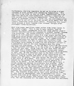
This diode haven't to do with the topic here - go toConceivably he was talking about the "Baxandall diode" that was used in the 1970's, to reduce (not eliminate) crossover distortion in quasi-complementary output stages. It's D1 in the attached figure (from JLH's "The Art of Linear Electronics").
http://books.google.de/books?id=Qpm...FQQ6AEwAg#v=onepage&q=baxandall diode&f=false
Last edited:
It seems to me that diodes used in parallel with emitter resistors are no longer useful for a hifi amplifier. In the past they may have helped to stabilise the quiescent current, in which case they were unbiased normally, and would have caused a non-linear change in gain when they turned on. If, however, they were biased as in the Baxandall circuit, and variations of that, they were similar in effect to a Vbe and needed thermal compensation. So, I agree that a Vbe multiplier, attached to the power transistor heatsink along with the drivers (how many old amplifiers used separate small heatsinks for the drivers??? - indeed, RCA even assumed such was the case with their 40409/40410 driver pair which had attached heatsinks to the TO-5 case) seems to provide adequate control. Dare I say I have not seen undue drift which makes me wonder about the need for diode-feedback transistors!
As for crossover distortion, I recommend following Cherry's approach with the basic amplifier architecture: changing the position of the Miller capacitor and adding a sprog stopper reduces crossover distortion so effectively that in a simulation I got almost the same performance from a quasi as a full complementary output stage.
John
- Status
- This old topic is closed. If you want to reopen this topic, contact a moderator using the "Report Post" button.
- Home
- Amplifiers
- Solid State
- Diodes instead of or across emitter resistors