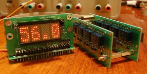
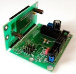
This is something that we (Peter Daniel and I) built – digital potentiometer with fully analog signal path. What's most important – input impedance is constant (excluding fist three steps) just like in normal pot.
Features:
- attenuation from -56.8 to 0dB
- completely passive signal path
- constant input impedance (set by resistor network: 10k, 20k, 50k, …)
- great display (used in Mark Levinson products)
- control type: infrared remote, buttons, encoders
- 6 input selector (additional mute output and on/off relay) connector
Attachments
I will calculate the cost, prepare the BOM list and let you know.
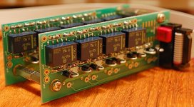
And for multichannel connection - yes, this is possible. As you can see there are two connectors that easily drive 4 or 6 channels simultaneously (maybe even 8 with darlington transistors).
And for multichannel connection - yes, this is possible. As you can see there are two connectors that easily drive 4 or 6 channels simultaneously (maybe even 8 with darlington transistors).
Attachments
This is an update to an older project on which we've been working together: http://www.diyaudio.com/forums/showthread.php?p=1118699
It was mainly inspired by Placette, however, I wanted more sophisticated control interface.
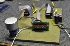
The original display that Veteran came up with was not practical, rather expensive and hard to source, so for months I've been persuading him to try something much easier to implement and better looking. And finally he did it")
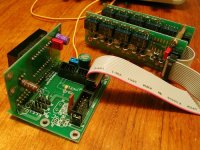
Picture below shows same display module and optical encoder as used in Levinson preamps.
It was mainly inspired by Placette, however, I wanted more sophisticated control interface.
The original display that Veteran came up with was not practical, rather expensive and hard to source, so for months I've been persuading him to try something much easier to implement and better looking. And finally he did it
Picture below shows same display module and optical encoder as used in Levinson preamps.
Attachments
The calculator was posted here: http://www.diyaudio.com/forums/showthread.php?p=840215 and you can use any resistor values (however, they need to multiply by 2). This calculator was created by Algar_emi.
Really nice! Too bad I just ordered a IR analog remote volume control for my B1...
Wait! I can actually use the motorized pot of the IR remote volume control to drive the encoder. The combination of 2 will be a match in haven. I want one too now
Daniel/Veteran maybe you can consider to offer a remote controlled version down the road. There are many coach potatos like me out there...
Last edited:
This actually is remote controlled version. The encoder does not need to turn, the volume adjustment is done within a microchip itself, that triggers the relays and display shows the actual attenuation value. You can also set muting (volume off) and select sources with a remote. Veteran also confirmed that the unit will remember previous setting after switching off/on.
Last edited:
Looks interesting alright.
My questions are the following:
Are we looking at 8 relays per channel in an r2r ladder or evenly stepped to give 8, 128 or 256 steps?
How many sets of relay contacts does a low level signal have to pass through?
Does the PIC shutoff once the volume is set?
Looks great- regards, john
My questions are the following:
Are we looking at 8 relays per channel in an r2r ladder or evenly stepped to give 8, 128 or 256 steps?
How many sets of relay contacts does a low level signal have to pass through?
Does the PIC shutoff once the volume is set?
Looks great- regards, john
There are actually 7 relays per channel: each relay works as bypass device for either series or shunt resistor. Attached schematic (courtesy of Veteran) shows how it works. The other 2 relays are there to provide additional steps for more attenuation (which normally would be rather coarse)
Attachments
- Status
- This old topic is closed. If you want to reopen this topic, contact a moderator using the "Report Post" button.
- Home
- Source & Line
- Digital Line Level
- Digitally controlled relay volume regulator