Post #9:
Some of the 4x21844S boards had 270 ohm and some had 330 ohm in the location of R30. The photo I looked at had the 270.
I wasn't aware that there was a driver board with 4 2184S ICs.
The schematic diagram shows a circuit that's not going to be reliable. It relies too much on the gain of Q13 (which will vary with temperature). R80 isn't going to act as a reliable voltage divider component because it's in series with a capacitor. A change in frequency would change its effect on the circuit.
Have you tried paralleling a short piece of small (16g) wire across the shunt resistors to see if that would stop it from shutting down (and confirm that the problem was indeed in the over-current circuit)?
Does the M4 amp use the same driver board for the audio?
i put the car on a 14.4volt, 100amp power supply. as the batteries charged and the voltage increased the amp became more and more prone to going into protect.
I'll hopefully have another fiddle with this tomorrow, its dark now.
I might try the amp with the sub simply disconnected, and see what happens.. its all very weird.
Based on pictures, the M4 controller is different to the Z1, but I haven't seen the M4 in person 🙂
I might try the amp with the sub simply disconnected, and see what happens.. its all very weird.
Based on pictures, the M4 controller is different to the Z1, but I haven't seen the M4 in person 🙂
I'm wondering if this amp is actually faulty now, somehow... but it really does only seem to turn off with higher voltage...
I assume that because the LED goes off completely, that the SG3525 is actually shutting down, not the protection circuit...
I'll try to pull the amp apart today, with it still wired up in the car, and get some voltage measurements off the IC...
Its too difficult to remove the amp, I probably should have tried to trouble shoot it before I installed it, but wasn't entirely sure that the issue would occur...
Older pic, can't really see the amps, but you get the idea.
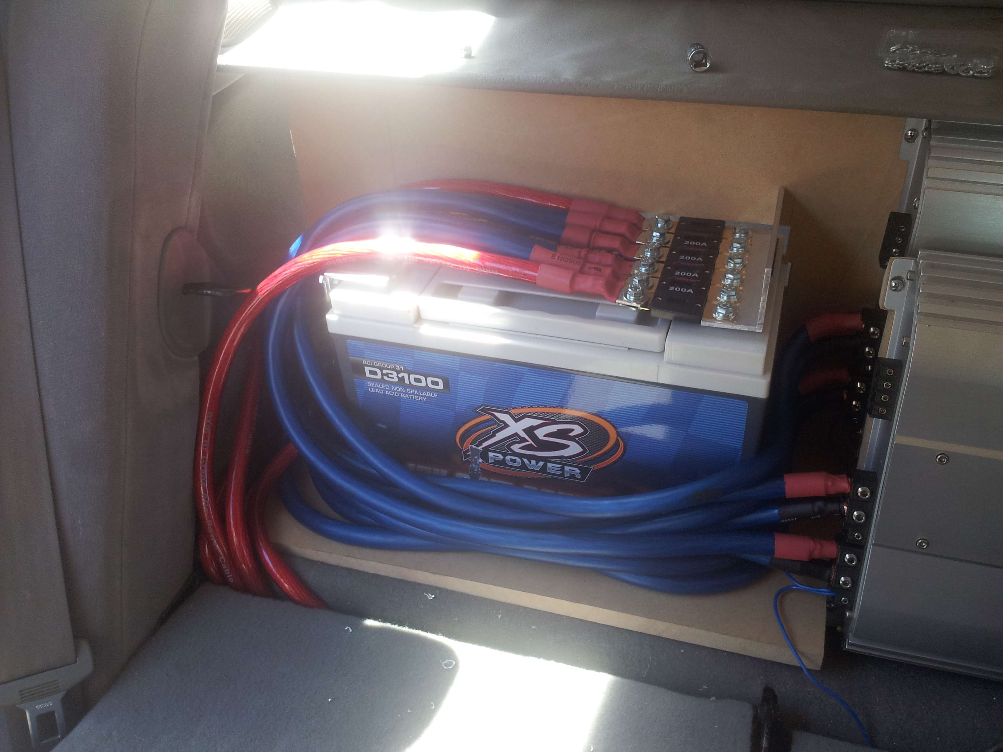
Fortunately its the front amp, so I can just undo the mounting screws and flip it forward, which I've done before as one amp reached clipping WAY before the other when I first installed them...
Going to use this thread as reference:
http://www.diyaudio.com/forums/car-audio/174907-digital-designs-z1.html
Maybe I've broken a component led too, which only goes open circuit when it warms up... and maybe it gets warmer with the higher input voltage 😉
maybe...
I'll try to pull the amp apart today, with it still wired up in the car, and get some voltage measurements off the IC...
Its too difficult to remove the amp, I probably should have tried to trouble shoot it before I installed it, but wasn't entirely sure that the issue would occur...
Older pic, can't really see the amps, but you get the idea.
Fortunately its the front amp, so I can just undo the mounting screws and flip it forward, which I've done before as one amp reached clipping WAY before the other when I first installed them...
Going to use this thread as reference:
http://www.diyaudio.com/forums/car-audio/174907-digital-designs-z1.html
Maybe I've broken a component led too, which only goes open circuit when it warms up... and maybe it gets warmer with the higher input voltage 😉
maybe...
disconnected subs, still shuts down, disconnected rca to the headunit, shut down once i believe... now Im sitting here, waiting...
plugged the rcas back in and it hasn't shut down yet, for at least 15 minutes. the thing is, its a pioneer headunit and i know the pico fuse is blown on the rca ground... is this going to cause a dc offset on the amp input and cause it to shut down...
looking at the schematic, it appears most of the preamp is grounded to the signal ground... the signal ground isn't connected to the power ground, and I know this from measuring it with a multimeter, not just from the schematic....
how can the amp do anything with no signal ground?!
how can the amp do anything with no signal ground?!
with the amp off, I measure about 1.8 ohm between the rca ground and the battery ground...
with the amp on, its more like 50 ohm...
looking at the schematic, it seems lots of things are connected to the "signal" ground...
with the amp on, its more like 50 ohm...
looking at the schematic, it seems lots of things are connected to the "signal" ground...
I don't know if the diagram I have is the same as your amp but on this version of the Z1, R229 and C299 are connected between the two grounds.
With the RCAs plugged in, you'd read less than the 1k ohms of R229.
The attached image is the plate from the service manual. Is it the same as the one you have?
With the RCAs plugged in, you'd read less than the 1k ohms of R229.
The attached image is the plate from the service manual. Is it the same as the one you have?
Attachments

R229 and C299 is correct, yes 😉
But the headunit rca ground measures open circuit to chassis ground, as the pico fuse has blown.... and it seems the amplifier really expects this to be tied to ground, otherwise, as you've pointed out, its basically floating (with a 1k resistor tying it to ground)
But the headunit rca ground measures open circuit to chassis ground, as the pico fuse has blown.... and it seems the amplifier really expects this to be tied to ground, otherwise, as you've pointed out, its basically floating (with a 1k resistor tying it to ground)
You need to repair the shield ground on the head unit if you're trying to find other problems. At the very least, jump from the shield on the RCA to the head unit case.
but is having the ground floating likely to be the cause of the issue?
the two modules on the board appear to have a "sync" connection between them, via an optocoupler.
one side of the opto uses the battery ground, the other uses the signal ground.
the two modules on the board appear to have a "sync" connection between them, via an optocoupler.
one side of the opto uses the battery ground, the other uses the signal ground.
Headunit rca ground measures as being connected to the case, and the ground pin in the plug...
ah... so why did the other end of the RCA cable measure as not being connected.... hmm..
ah... so why did the other end of the RCA cable measure as not being connected.... hmm..
I dont know whats going on...
rca metered fine, so then I measured the rca headunit power (ground connection) plug, to ground... about 10 ohms.... well that isn't right...
measured from battery negative to headunit ground, 130ohms? I assume its not really 130ohm, but that voltage drop along the cable causes the odd reading?
rca metered fine, so then I measured the rca headunit power (ground connection) plug, to ground... about 10 ohms.... well that isn't right...
measured from battery negative to headunit ground, 130ohms? I assume its not really 130ohm, but that voltage drop along the cable causes the odd reading?
Last edited:
there's voltage drop between the headunit ground, and the battery ground.... and if you turn the headlight on, the drop increases (about 50mv max)
the reason I measured ~50ohm to ground at the amplifier, and assumed the picofuse was blown, was because the voltage drop resulted in weird resistance readings...
the reason I measured ~50ohm to ground at the amplifier, and assumed the picofuse was blown, was because the voltage drop resulted in weird resistance readings...
voltage drop just disappeared... 🙁 now the headunit measures 0ohm to ground, as it should....
me thinks something isn't right in the cars wiring... going to ground headunit straight to battery
me thinks something isn't right in the cars wiring... going to ground headunit straight to battery
new ground to the headunit (there was a 4ga cable running behind the centre console to the front stage amp under the front seat) so I just spliced a 12ga cable into that...
Now the rca ground measures 0 ohm to the battery ground....
I'm pretty sure this was the issue....
ever so slightly intermittent ground on the headunit, resulting in a 50mv difference between the rca ground and the battery ground...
Now the rca ground measures 0 ohm to the battery ground....
I'm pretty sure this was the issue....
ever so slightly intermittent ground on the headunit, resulting in a 50mv difference between the rca ground and the battery ground...
Amp hasn't shut down since... Now to see if it actually goes into short circuit protection when wired at 0.5ohm! Which my friends M4's definitely do.
Amp shut down once yesterday on a 10 minute drive... if only they had multiple LEDs for each protection circuit!
I played music flat out while driving for about 30 seconds to a minute, no worries, turned the volume down, bass kept going, track ended, next track started... no bass.. few seconds later I heard the click of the relays coming in, and had bass again....
hmmm...
I played music flat out while driving for about 30 seconds to a minute, no worries, turned the volume down, bass kept going, track ended, next track started... no bass.. few seconds later I heard the click of the relays coming in, and had bass again....
hmmm...
- Status
- Not open for further replies.
- Home
- General Interest
- Car Audio
- Digital Designs - Z1, removing short circuit protection?