Cool!
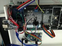
Yes, I have PurePath Console (PPC) GUI, I also have the PurePath Console Motherboard (as well as the TAS5548EVM).
Don't know if it helps, but the TI "Soundbar Reference Design" EVM includes code for the onboard MSP430 to load parameters/biquads as well as read RC5 IR and handle volume control, source switching etc. link here: PCM3070RHBEVM-K Evaluation Module - PCM3070RHBEVM-K - TI Tool Folder
Cheers,
Mike
Discussion here: TAS5548EVM - device configuration on powerdown/powerup - Audio Amplifiers Forum - Audio Amplifiers - TI E2E Community
Cheers,
Mike
Cheers,
Mike
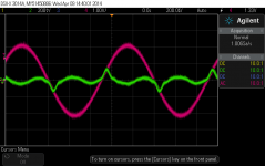
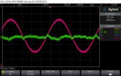
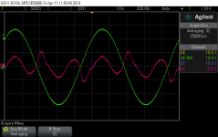
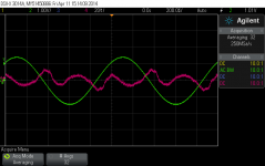
Here are measured waveforms of the digital amp. The amp is powered by a regular 12 V SMPS. A 1 kHz of 2 Vrms was driving a 4 R load (USB to I2S done by USBStreamer). The output was connected to AP Portable One. THD+N was about 0.1 % (BW = 22 Hz to 22 kHz). Distortion residual is shown in the left picture below. Right picture shows 100 Hz distortion residual (THD = 0.022 %).
I will use AP-S1 to send digital signal to the board and get more data later including FFT of the output.
I will use AP-S1 to send digital signal to the board and get more data later including FFT of the output.
Attachments
Last edited:
distortion residual
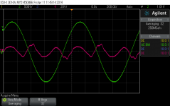
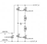
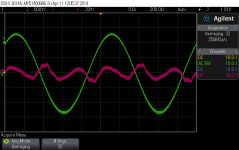
Distortion residual of two different output inductors are shown below. The inductors are Wurth high-current shielded SMD parts. For 22 uH, THD is 0.13% (1 W, 4 Ohm). For 10 uH, THD is 0.097 %. THD difference is not much at all. Distortion residual does show different shapes.
Left photo: 10 uH, middle photo: 22 uH
Filter capacitors: C80 = 2.2 uF (film), C82 and C83 = 1000 pF
Attachments
")
PM sent re a board if you have any left.
thanks
Got it. I am just back from an one-week vacation.
I'm running no output filter on my Purepath class D amps
The circuit board arrived today - thanks!
Cheers,
Mike
Great to hear you received the board!
No output filter at all!!! Is your Purepath amp connected to a single driver or a loudspeaker with passive crossover?
Single driver(s). Read about the benefits here: www.ti.com/litv/pdf/sloa023
Can you please PM me the Arduino code?
Thanks!
Mike
Can you please PM me the Arduino code?
Thanks!
Mike
panson_hk: can you do a frequency respons for the different outputfilters you showed for THD above? I expect more difference there if load is constant 4ohm.
Sure! I will do that.
Post the schematic, BOM and layout artwork files here for convenience.
Thank you!
- Status
- This old topic is closed. If you want to reopen this topic, contact a moderator using the "Report Post" button.
- Home
- Amplifiers
- Class D
- Digital Amplifier Project