Hi Guzzler,
It took me a while to gather all my "yellow pages" and edit an document. I hope it is clear enough and it makes sense to you and anyone else interested. It was a good exercise for me and at some point I just couldn't stop editing so now I have to split it in two parts due to the upload limit. If you got any questions....
To Andrei: nice compact layout. I notice some good polymer smd electrolytics and some pps film caps. What is the application of your DAC - because I see only an optical input and two unipolar supplies?
First part:
Attachments
Actually in this part there are some examples of differential filters (and some personal ramblings about this subject). As a rule of thumb the higher the filter order and the higher the cutoff frequency the better it is. Of course we still need some attenuation at 352k or 384k and a very good GBW for the OpAmp in this case.
But since in the MFB topology with a single OpAmp we can't get either Bessels or (even) Butterworth filters for orders greater than 3....most likely you can settle for an fc=80k-90k.
Well... let us know your results
Second part:
But since in the MFB topology with a single OpAmp we can't get either Bessels or (even) Butterworth filters for orders greater than 3....most likely you can settle for an fc=80k-90k.
Well... let us know your results
Second part:
To sidiy: The analog audio signal is coming out on three-pin headers on the right...
About filters: The simplest I/V converter is passive - a (small value) resistor. One can incorporate a 3rd order passive low-pass filter by having RC-L-RC chain (see PCM1730 schematics above for differential version). But the neatest trick is to use the leakage inductance of a step-up transformer as a filter element. This solves the problems of impedance conversion, voltage step-up, diff/se conversion, common mode rejection, and low-pass filtering in one passive circuit with five elements (well, seven if the input is differential). Add a opamp output buffer/gain stage, an you'll be set...
About filters: The simplest I/V converter is passive - a (small value) resistor. One can incorporate a 3rd order passive low-pass filter by having RC-L-RC chain (see PCM1730 schematics above for differential version). But the neatest trick is to use the leakage inductance of a step-up transformer as a filter element. This solves the problems of impedance conversion, voltage step-up, diff/se conversion, common mode rejection, and low-pass filtering in one passive circuit with five elements (well, seven if the input is differential). Add a opamp output buffer/gain stage, an you'll be set...
Hi Andrei,
Sounds interesting and worth considering. For one I never tried passive I/V and higher order passive filters. Trouble is that I wasn't able to see all the component values on the PCM1730 DAC schematic. Can you show us a schematic for the analogue stage and some details about building/procuring the transformer, insertion loss of the passive filter/or the gain of the THS4131? Tks.
Sounds interesting and worth considering. For one I never tried passive I/V and higher order passive filters. Trouble is that I wasn't able to see all the component values on the PCM1730 DAC schematic. Can you show us a schematic for the analogue stage and some details about building/procuring the transformer, insertion loss of the passive filter/or the gain of the THS4131? Tks.
It’s fair to say that a transformer is quite an elegant way of solving the problem, however, the prices for good transformers are way more than I’m prepared (or can afford) to spend. Using the Lundahl transformers that a lot of people recommend, you’d be spending nearly £120 just on two components, whereas you could build the whole thing for £120 with some spare change using either an active stage or a passive stage like andrei (and another vote for component values ") )
)
)True, transformers are expensive and big... But I still like them .
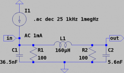
The basic passive I/V with 3rd order lowpass topology is shown on attached schematics. For Bessel filter response, set R1 = R2 = R, L = 0.1544617529*R/f_3, C1 = 0.3506838218/R/f_3, C2 = 0.0537022973/R/f_3, where f_3 is -3dB corner frequency (the values on the schematics are for f_3=96kHz Bessel). The impedance seen by the DAC current output is R/2 in passband, and decays at high frequencies (it is never bigger than R/2). The voltage at the filter output is Idac * R/2. The gain of THS4131 is set by the feedback loop resistors (check datasheet for recommended values); you can pull a gain of 10 comfortably.
.The basic passive I/V with 3rd order lowpass topology is shown on attached schematics. For Bessel filter response, set R1 = R2 = R, L = 0.1544617529*R/f_3, C1 = 0.3506838218/R/f_3, C2 = 0.0537022973/R/f_3, where f_3 is -3dB corner frequency (the values on the schematics are for f_3=96kHz Bessel). The impedance seen by the DAC current output is R/2 in passband, and decays at high frequencies (it is never bigger than R/2). The voltage at the filter output is Idac * R/2. The gain of THS4131 is set by the feedback loop resistors (check datasheet for recommended values); you can pull a gain of 10 comfortably.
Attachments
 Hope the Behringer thing won't win over.
- Status
- This old topic is closed. If you want to reopen this topic, contact a moderator using the "Report Post" button.
- Home
- Source & Line
- Digital Source
- Differential I/V stage? And RX input