Not putting down what Tmyr had done;
i think that it is a very good exploring piece of speaker!
If any of the "commercial" units sounds worse than what he has .... i don't see how a company could get out with that unless Tmyr has just found a miracle recipe!
can't wait to build my own ..
i think that it is a very good exploring piece of speaker!
If any of the "commercial" units sounds worse than what he has .... i don't see how a company could get out with that unless Tmyr has just found a miracle recipe!
can't wait to build my own ..
I must say I agree with v-bro and tmyr in using this pre-made film as a prototyping medium, likely to be replaced by a more appropriate film at a later date.
All of my DIY projects seem to take a rather long time between inception and realisation. Now, step up transformers, mylar and the like aren't going to expire just sitting around waiting for me to get my act together. It would be a shame to not use the coating liquid in time, or worse, have some problem with your panel after it has been in use for a while, only to find your coating liquid has gone bad and you have to get more just to replace the panel. Or, what if you want to play around with different panel sizes?
How come the ESL DIY suppliers don't make a pre-coated film? Is it simply because the conductive materal should stop at the frame edge?
Tmyr, perhaps you could use an iron (for pressing clothing) to transfer the coating off the film and onto paper. I would think the iron should be against the paper, rather than the film.
Max
I ordred some Lycron spray can
doesn't expire ( as far as i know )
was told that it's performance is adequate
it costed 36$USD + shipping
and i'll have it laying aside until i get to the point of building my unit
then for the diaphragm
i got some Mylar sample shipped to me directly from Dupont a few years back
i'll have to check out if it is really what i want now
but you can always buy some polyester film for pretty cheap in small quantities on the internet
 ..Wonderfull ..
.. i really cant find anything to dissagry with anyone . you have all made strong and justifiable points . now i can even make some additional conclusions .:
. every maker uses his own ink compound and membrane, it only happens that to achieve same specs they have to use more or less the same chemicals . they seem to use Mylar like film 4~8ì and that carbon black thing wich conducts, with waxes to melt at a temperature and stick to paper . so exact properties for our use of a given product cannot be known until after purchase . luck is not something i like to mess with when it comes to money ..
. given the films commercial width dimension it is almost impossible to strech it mechanicaly and have acceptably wide panel . heat streching will not give the tension most people say they desire . .
. it is nice for long term stability the coating not to reach spacer . impossible for this ink film matterial . but . i feel that with high resistivity coating and a small point contact to charge membrane its difficult to equally distribute the charge over the entire surface , especialy with voltages above 3 some Kv's the charge fly's away to the air leaving less charge on surface as you go further from that point . i noticed this with my high res. graph coating where my screwdriver was sparking at the membrane near the perimeter but not in the middle area . thats why i used the "diffuser ring" approach to minimise this effect compromising long term dirt-leakage stability (i dont realy care for a 30yr use). one could use "dust cover" approach as QUADS do maybe compromizing clarity ..
. my main goal here was to have a nice "free" ride wich makes it even more enjoyable for my specific personality . zero money were spent for an astonishing to my experience result and the film discovery was a great solution to a big problem for nothing . i was limited to 15ì packaging film and graphite and now i have 4ì Mylarlike factory coated film @ favorable resistivity i can immediatly use . seems to me like a gift from above ..

.. i will now refilm other panel with depleted ink version to hear how 4ì's sound .
I don't think it is much of a problem if the conductive ink extends to the (inner-)spacer. But it would be nice to remove part of it which is 'on' the spacer. So you won't have any conductive parts that stick out of the sides of your ESL and touch the frame assembly. Since the frame is usually made from wood (conductive) you don't want any conductive membrane to touch it.
The easiest way is to glue the membrane first on the uncoated side (best adhesion!). After that you can remove some of the ink with for example thinner (outdoors, unhealthy vapours). You can reduce stray capacitance as well by not driving the area which can't move.
The easiest way is to glue the membrane first on the uncoated side (best adhesion!). After that you can remove some of the ink with for example thinner (outdoors, unhealthy vapours). You can reduce stray capacitance as well by not driving the area which can't move.
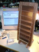
.. and presto .
. here it is . the depleted thinner version .
. not opaque any more . ~1MÙ @ 1 inch
. carefull listening will show vertues regarding sound detail.
. at 1st minute listening i'm pleased enough.
. film resonance is low, somewhere it can't hurt my feelings.
. i surely need 1mm aditional d/s distance and some more charge to make some room for bass notes to feel more comfortable.
. overall its way better than graphite regarding performance and ease of use.
. cheers
Attachments
maxro said:All of my DIY projects seem to take a rather long time between inception and realisation.
But after the first.....

Tmyr, I was thinking of a different method to stretch the membrane. How would the result be if you stick four bars on the edges and put triagular pieces in the corners (like a frame for an oilpainting...) And at the right tension stick/fix the stators with spacers on the membrane and cut off the edges and bars....
I checked out the other (bad working) ESL-57 treble panel (dustcovers allready removed), I can't measure any conductivity on the membrane. Also the stators apear to be made of non conductive material (DMM works fine on real resistors, it's a Fluke 10...) I guess the stators are fitted with conductive layers inside the panel. Only the panel is put together with rivets and I fear I will damage the stators with drilling them out. By probing through the holes in the stators I tried to measure the membrane, maybe I should make more contact area.. Anyway the tension still feels pretty tight when I push on the membrane (the 9.5" wide membrane is devided in three very narrow areas, the rivets are also mounted in the stripes that form the division).
Soon I want to open it up and post some pictures of it...
Another thing I was thinking, maybe the ink can be removed by a solvent and make a good EC coating by spraying it back on after the film had been cleaned allover...Don't know if it's feasible or makes sense at all, but it might help getting the right resistance/conductivity.
After I built panels that work well on the quad supply and stepup I want to go for those funny little psu's from emco. Still dream about the idea of a custombuilt core for a stepup transformer, afterall I am a small mechanics engineer..I can weld and at work there is a metal workshed (with all kinds of metal machining equipment). I thought of a possibility to fit existing PSU tranny coils on the core, that way 'cowboying' the idea. And make a tranny that is double c core. At work I also have a lot of electronics measuring equipment, only I
need some formulas to calculate things. Or maybe all this is a stupid idea afterall, please inform me...

v-bro said:Also the stators apear to be made of non conductive material (DMM works fine on real resistors, it's a Fluke 10...) I guess the stators are fitted with conductive layers inside the panel.
Yep, there is some kind of graphite paint under the grey isolation paint ojn the inside of the panels. And only 0.5 mm between that and the membrame
See the need for overvoltage protection ? Only the panel is put together with rivets and I fear I will damage the stators with drilling them out.
You're right, be carefull with drilling, the plastic melts easily fromthe heat generated. Also the rivets tend to turn along with the drill bit.
Better use a pair of small pliers to pinch them twice, under 90 degree angle, then you can push them out to the other side. Worked fine for me. I replaced them with M3*8
By probing through the holes in the stators I tried to measure the membrane, maybe I should make more contact area..
Don't expect any reading with normal DVM, resistance is in the giga Ohm range so way out of range.
To measure such high values you can use the method in the picture, set the meter to mV. It forms a simple voltage divider, when you know input resistance of the DVM you can calculate membrame resistance.
Anyway the tension still feels pretty tight when I push on the membrane (the 9.5" wide membrane is devided in three very narrow areas, the rivets are also mounted in the stripes that form the division).
It is very tigth indeed, I suspect because of the very small spacing. I had to stretch my new membrames to the breaking point to get things working properly... Btw the three sections are isolated from each other (conductive paint is applied in three parts) so that the middle one can be used as tweeter, the outer two are connected externally to form the midrange. So where there are rivets there is no paint. Well it couldn't work otherwise as the rivets would shorten the membrame to the stators.
Still dream about the idea of a custombuilt core for a stepup transformer, afterall I am a small mechanics engineer..I can weld and at work there is a metal workshed (with all kinds of metal machining equipment). I thought of a possibility to fit existing PSU tranny coils on the core, that way 'cowboying' the idea. And make a tranny that is double c core. At work I also have a lot of electronics measuring equipment, only I
need some formulas to calculate things. Or maybe all this is a stupid idea afterall, please inform me...
Ok
Well, you can't make a solid transformer core, the core itself can be seen as a shorted turn so you don't want it to be conductive. Core losses will be massive with solid cores.
Look at existing transformer cores and you will notice that they are made of thin strips laminated together. There is isolation in between the laminations and the material is iron with very high silicium content to increase resistance. All to make the losses due to eddy currents as small as possible.
So, to diy your own trannie you have to source some factory made cores.
Attachments
A couple of comments in no particular order:
tmyr: Do you have a high value resistor between your power supply and panel? That actus as a barier to slow the charge migration into and out of the power supply and makes the cell work in "constant charge" mode. It's not as big a deal with high resistance coatings, but with really low resistance coatings like the fax film (f'ing brilliant by the way, and I just threw away two rolls of the stuff) it does get more important. I have 20 megohms on my big panels.
A comment about quality: Quality stuff can be critical to success. For example I bought Seas excel woofers for my transmission line bass modules. I was concerned with how well the bass would integrate with the panel even at the couple hundred Hz I was planning on using (130 Hz now). so I bought the best performing woofer I could find, regardless of cost (within reason). It turns out that I wasted my money and could have gotten as good a performance from the lower Seas metal cone line.
I bought transformers from roger sanders, which are pretty plain looking EI core units but he said they really were quite nice. After getting the speakers built, I bought a set of Plitron toroids and swapped them in. For my 130 Hz and up, there wasn't much of a difference at all. In fact I've still got the EI core units in place and the Plitrons in a box.
Quality is important and in many cases it can make your life easier, you can buy your way out of limitations from lesser products. But in many cases, the price difference is for features or aspects that aren't important for your intended use. I suspect if I was building a full range ESL, the plitrons would kick the living snot out of the EI core trannies, but above 130 Hz they don't. And the multiple copper shorting rings that I paid for in the Seas excel woofers are for better midrange performance which I'm not using.
Sheldon
Interesting interesting interesting!
I tried a couple of rivets with the 90 degree pinch and it works fine, thanks to you Maudio! And thanks for the attachement...
Why do 57's use this stator technique, does it make much difference how thick the (conductive part of) the stators are?
I guess I also understand the overvoltage protection issue better now, the conductive layers on the stators (actually being the stators) are connected to the wires by another rivet with a soldering tag. I still didn't open the whole panel (a lot of rivets, don't have the time now...). But I figure the layer can melt through around the connection to the rivet...right? Than that division won't produce sound anymore...not? Or will the membrane be the first to go?
I never turn up the volume far beyond the point where I hear distortion, but tried many times and turned it down reasonably quick. Isn't it strange they're not damaged yet?
Tmyr, I admire your work a lot and think the construction of your wire stators is a piece of art allready to look at...really really curious what they sound like....
Have to admit I sometimes enjoy listening to "lesser" sounsystems too. Some pretty cheap setups that are kept simple can be so charming. The small fullrange cone speakers I built (see my avatar) produce quite sweet sound and I easily forgive the colorations on some ocasions, but when I want to hear every little detail and sit in my listening chair The ESLs are indispensible...
So I was thinking of making an ESL tweeter to add to a little woofer to try to operate it on batteries. And make the round shaped panel to perhaps beat the 57's...
By the way Sheldon, How are these metal cones? I never liked metal dome tweeters, but suspect a metal cone woofer can be an interesting mate with my panels.. I have a design in a magazine here (elektuur luidspreker special, can't find it for the moment..) called ribbon+, it uses a Bandor alu cone and they were very positive on the soundquality of this alu cone. The cabinet had a ribbon on top the size of the tweeter section of my 57's (about 2.5x50 inch).....
I wonder, can a tweeter stepup tranny be smaller? (I will forget about diy-ing one for the moment, though I did wind a lot of filter coils on existing cores...)
I tried a couple of rivets with the 90 degree pinch and it works fine, thanks to you Maudio!
And thanks for the attachement...Why do 57's use this stator technique, does it make much difference how thick the (conductive part of) the stators are?
I guess I also understand the overvoltage protection issue better now, the conductive layers on the stators (actually being the stators) are connected to the wires by another rivet with a soldering tag. I still didn't open the whole panel (a lot of rivets, don't have the time now...). But I figure the layer can melt through around the connection to the rivet...right? Than that division won't produce sound anymore...not? Or will the membrane be the first to go?
I never turn up the volume far beyond the point where I hear distortion, but tried many times and turned it down reasonably quick. Isn't it strange they're not damaged yet?
Tmyr, I admire your work a lot and think the construction of your wire stators is a piece of art allready to look at...really really curious what they sound like....
Have to admit I sometimes enjoy listening to "lesser" sounsystems too. Some pretty cheap setups that are kept simple can be so charming. The small fullrange cone speakers I built (see my avatar) produce quite sweet sound and I easily forgive the colorations on some ocasions, but when I want to hear every little detail and sit in my listening chair The ESLs are indispensible...
So I was thinking of making an ESL tweeter to add to a little woofer to try to operate it on batteries. And make the round shaped panel to perhaps beat the 57's...
By the way Sheldon, How are these metal cones? I never liked metal dome tweeters, but suspect a metal cone woofer can be an interesting mate with my panels.. I have a design in a magazine here (elektuur luidspreker special, can't find it for the moment..
) called ribbon+, it uses a Bandor alu cone and they were very positive on the soundquality of this alu cone. The cabinet had a ribbon on top the size of the tweeter section of my 57's (about 2.5x50 inch).....I wonder, can a tweeter stepup tranny be smaller? (I will forget about diy-ing one for the moment, though I did wind a lot of filter coils on existing cores...)
The seas woofers are amazing down low. They have an insane breakup mode that is like 20 dB high, but that's up in the midrange. Those drivers are great if you notch the living crap out of the breakup region. Because I'm actively crossing over the woofers so far away from that region, I didn't bother doing anything with it. Not turning on the panel amps and listening, there isn't anything beyond bass coming out of my woofer boxes. Thump thump thump.
The quads are an interesting design, quite unique from anything else out there. Really outstanding bit of engineering when you consider the limited materials they had to work with back then. The treble panels will arc at about 3KV give or take (the quads don't have the tightest manufacturing tolerances out there). The treble panels have the conductive portions painted inside the stators, and the bass panels have the conductive regions painted on the outside of the stators. The entire membrane is covered in a conductive coating which in many cases has disappeared over the decades (again, they didn't have the materials and coating methods we have now)
The attachment points are metal tabs riveted to the plastic and the conductive paint covers the rivet. When soldering to those tabs, be very quick.
You may want to try an experiment where you put cardboard baffles on the sides of the treble panel to imitate the width of the speaker, you'll find that the panels will play a whole lot lower and you won't have a hole in your midrange.
Sheldon
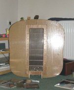
.. aaa a baffle is a very interesting accesory and it does lots of work preventing compressed air from the forward movement of the membrane go around the frame and hit membrane at the back helping forward movement some more . simple words aerodynamicaly speaking but this is the case as i persive it.
using it helps extend bass region (less dipole canselation) and reduce membrane movement thus more spl in general _if u have the additional amp power that is..
such a baffle should be heavy as it is hit from both sides with opposite air presure and is prone to vibrate.
my experiment showed the bennefits of a baffle and the weeknesses of a light carton constraction.
the whole idea is not that beautifull . maybe thats why people dont use it much . but is very effective..
can make your esl sound bigger depenting on the size of that baffle ..
stokessd .. yes i use a "DALE ROX-2 40MÙ GK" cyan in color big (for hv) resistor .. another nice find at work.
Attachments
Baffles extend the frequency response downward but they don't provide any higher SPL. That's why most people go with larger speakers instead of small ones with baffles. If you've accepted the idea of putting a 3' wide speaker in the room, why not make it 3' of active speaker instead of 1' of speaker and 2' of baffle? Guess which will play louder...
I_F
I_F
Baffles extend the frequency response downward but they don't provide any higher SPL. That's why most people go with larger speakers instead of small ones with baffles
yes indeed this is absolutly true ..
i was refering to a given speaker wich could improove its performance with this accesoir - not design and constract a baffled one . if baffle reduces membraine movement (x-nominal) then you could drive it with some more watts to make panel play louder .
Yup, me... I will try Sheldon, thanx. But where would it aproximately roll
off? A field-soundengineer from work measured the freq spectrum of the whole system (with woofer) in my very room and it didn't look bad...He used some very small professional field-spectrum analizer...aprox. 1 meter distance, several angles...
I don't like the idea of baffles, would small baffles pointing to the rear (from the sides). do the job? (like a U-shaped baffle...) Littlebit of (thin, breathable) foam glued behing it (between the edges of the baffle)?
Thanks....
- Status
- This old topic is closed. If you want to reopen this topic, contact a moderator using the "Report Post" button.
- Home
- Loudspeakers
- Planars & Exotics
- ..didn't know how they sound till i made me one..