This thread is a continuation of a discussion going on in the thread
about Per-Anders' CFB headphone amp. Since this started to turn
into a long threadjacking, I decided it was appropriate to do as
pavel suggested and start a new thread. Maybe the moderators
will try to move some of the old discussion over here.
The topic that arose and is the topic of this thread is the suggstion
to use CFP outputs in Diamond buffers instead of ordinary followers.
Maybe the topic is about CFP outputs in general too, we'll see.
I have now done some more simulations to compare the two types
of buffers. I did a number of experiments yesterday, but it turned
out that in both cases the distorsion is so low that I had to increase
the resolution of the transient analysis to get a reasonable noise
floor. The simulations now take about two hours each on my machine,
so I only have two basic cases to present for now.
Since the main point was CFPs in the output stage vs. followers as
in the standard version of the diamond buffer, I have started with
a rather idealized case to try pinpointing the effects of this difference
only. I use ideal BJT models with only IS and BF specified and I use
ideal current sources in the input stage. The results seem to correlate
rather well with PMAs claim of a tenfold improvement in distorsion
when using CFPs.
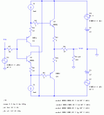
Below follows the circuits I simulated. First the standard buffer
Note that the BJT models used for the input stage are intended
to be similar to small-signal devices and those for the output stage
similar to power devices.
Attachments
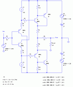
And here is the CFP version. I use the small-signal type of BJT for
the "drivers" of the CFP pairs, and the power type for the "boosters"
(or output devices).
Also note that for both buffers, the pairs are perfectly complementary
by using ideal models.
Further note that I had to increase the emitter resistors in the input
stage to get approximately the same bias current in the output stage
for both cases. Both buffers run in class A with approximately 34mA
quiescent current through the output emitter resistors.
Attachments
I used an input source of 5V pk, 10kHz in a 100 Ohm load (or 110
Ohm if one counts also the 10 Ohm "isolation" resistor) in order to
get rather high distorsion figures. The simulation was done using
a 21 cycle transient analysis, discarding the first cycle, and with a
mnimum time step of 100ps. I then ran a FFT on the input and
output signals using 0.5Mpoints and no windowing. There is no
trace of even-order distorsion at all when using perfectly
complementary transistor pairs, which concurs with earlier
experiments I have done on the effects of mismatching transistors.
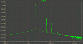
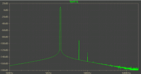
The odd-order distorsion for the standard buffer is approximately
as follows:
3rd: -79dB,
5th: -106dB,
7 th -132dB
and the spectrum looks like this
Attachments
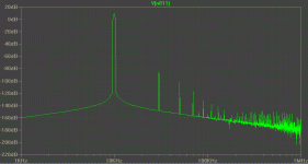
For the CFP version the distorsion figures are
3rd: -96dB,
5th: -112dB,
7th: -128dB
and the spectrum looks as below. There is more noise in this case.
For some reason the noise is present already in the input signal
which I don't quite understand since Spice uses ideal voltage
sources. Maybe it is some roundoff errors or some FFT artifact.
Hence, the higher order products are less reliable here, but we
clearly have a lower 3rd order distorsion than in the standard buffer,
but maybe there is a tendency towards slightly higher values for
high-order harmonics. The latter could be due to the noise artifacts
too, though.
Furthermore, please note that these are not to be treated as
absolute figures reflecting a real circuit, but only an attempt to
study the relative effects of followers vs. CFP outputs.
Attachments
Christer,
nice work. Probably noise about -150dB level is not so important. Have you tried to increase R1 and R2 to get higher quiescent current? I would guess that this could lower THD values. And maybe decrease R3 and R4 values. This might be pretty tricky work to find an optimum.
Regards,
Pavel
nice work. Probably noise about -150dB level is not so important. Have you tried to increase R1 and R2 to get higher quiescent current? I would guess that this could lower THD values. And maybe decrease R3 and R4 values. This might be pretty tricky work to find an optimum.
Regards,
Pavel
PMA said:Christer,
nice work. Probably noise about -150dB level is not so important. Have you tried to increase R1 and R2 to get higher quiescent current? I would guess that this could lower THD values. And maybe decrease R3 and R4 values. This might be pretty tricky work to find an optimum.
Regards,
Pavel
Maybe I have on some earlier occasion, with less resolution in
the simulation, but I think not. Both buffers seem to stay well
within class A, but maybe some more margin
would help. I might try that and maybe some other things, but it
is a bit tedious to do too many experiments when so long simulations are required to get useful data.
I did some experiments with R9 and R10 yesterday, but in shorter
simulations, where it was harder to distinguish noise and distorsion.
I tried 10, 100, 1k and 1G and out these values, 100 Ohms seemed
best, but the noise made those simulations less reliable for
comparisons.
Another question is also whether even these two types of
ideal BJTs are a reaonable combination.? Maybe the IS differs
too much to correspond to a realistic combinations? Well, anything
close to realistic would have to include a lot more parameters
anyway.
Thanks Christer, very interesting!
Maybe you can find the time to post some AC-plots with gain and phase also? You would need to use "real" transistor models for this though.
I don't think you should worry to much about the high-frequency noise. This is an artifact of the FFT. In the FFT window try switching between "Using extent of simulation data" and "Specify time range". In the text-box change the 4.999998ms to 5.0ms (numbers for example only, I think you see what I mean).
Hi Christer, All,
My carbon-based circuit simulator did see Ibias=5mA and calculated the output half's Iq to 10Ohm/5Ohm*5mA = 10mA, which must be wrong if it is in class A for +-5v into 100 Ohm.
I'll have to see it in my SPICE do get a better understanding.
In the meantime, and for a comparison look at this strange mutant of a diamond:
PDF: http://www.linearaudio.de/scratch/xdmnd-5.pdf
(Also attached, zip includes netlist and SWCad .asc)
I've used the BC850/860 models from Per-Anders' amplifier (and mixed two different manufacturers to avoid artificial symmetry) and BD139/BD140 models from Fairchild.
THD at 10kHz (5V into 100Ohm) is 0.0015%, about 97dB.
So what does this tell us? I'll test some other permutations before I try a judgement.
Regards,
Peter Jacobi
Christer said:They both run in class A. The load current swings about 45mA pp,
the current through the emitter resistors stay above 12mA all the
time and for the CFP case, the Ic of the power transistors stay
well above 5mA all the time.
My carbon-based circuit simulator did see Ibias=5mA and calculated the output half's Iq to 10Ohm/5Ohm*5mA = 10mA, which must be wrong if it is in class A for +-5v into 100 Ohm.
I'll have to see it in my SPICE do get a better understanding.
In the meantime, and for a comparison look at this strange mutant of a diamond:
PDF: http://www.linearaudio.de/scratch/xdmnd-5.pdf
(Also attached, zip includes netlist and SWCad .asc)
I've used the BC850/860 models from Per-Anders' amplifier (and mixed two different manufacturers to avoid artificial symmetry) and BD139/BD140 models from Fairchild.
THD at 10kHz (5V into 100Ohm) is 0.0015%, about 97dB.
So what does this tell us? I'll test some other permutations before I try a judgement.
Regards,
Peter Jacobi
By popular demand, well from Pavel at least  , I decided to give
my computer a rude awakening and run another 2 hour session.
I increased R1 and R2 to 60 Ohms in the standard version of the
buffer (ie. not the CFP version). This approximately doubled the
output stage bias to 72.4mA and it thus runs very very much in
class A, the current through the output devices now stays above
50mA all the time under the same conditions as the previous runs.
As expected, this improved the distorsion figures, which are now
3rd: -99dB,
5th: -137dB,
7th: -164dB
and the spectrum supplied below.
Note however that the comparison is no longer fair since both
buffers were biased almost exactly to the same current in the
previous runs. Doubling the bias current for the CFP version would
most certainly also improve its distorsion figures. However, this
may indicate that for low-level applications it could be better to
use the standard variant and dissipate some more power than
to increase the circuit complexity and risk stability problems etc.
In these examples each output device dissipates 0.5W at the
lower bias level and 1W at this higher level.
Attachments
ojg said:Thanks Christer, very interesting!
Maybe you can find the time to post some AC-plots with gain and phase also? You would need to use "real" transistor models for this though.
I don't think you should worry to much about the high-frequency noise. This is an artifact of the FFT. In the FFT window try switching between "Using extent of simulation data" and "Specify time range". In the text-box change the 4.999998ms to 5.0ms (numbers for example only, I think you see what I mean).
I have on earlier occasions done phase/frequency simulations for
the standard buffer, which is very well behaved. I have not done
so for the CFP buffer. That would be interesting and important to
do, but for the moment I prefer to concentrate on the comaprison
of distorsion using idealized BJT models. As soon as we bring in
models of real BJTs we add a lot of parameters and the results
will vary a lot depending on which ones we use.
It is not so much the high-frequency noise that bothers me, that
always turns up as an FFT artifact. What puzzles me is that with
all parameters equal, the actual input signal itself gives so different
noise floors when changing the circuit topology. It is measured
directly at the source and since Spice signal sources are ideal
with zero impedance, it shouldn't matter, at least in theory. Of
course, a simulation isn't theory either, it is reality, but a different
reality than a real circuit.
Hi Christer,
Thanks for your long simulation runs again!
I wouldn't call this unfair, see below for the reasoning. I'm more worried about the infinity VAF transistors, if at all.
What's fair and whats unfair, depends on which requirements are modeled here. For my intentions, this would be.
Base point is the pure diamond 15V mains +-5V signal into 1k load, running 5mA Iq, using fine small signals devices.
Now three different methods of going to 100Ohm load are compared:
a) everything stays the same, will run in class AB
b) larger, lower beta devices substitued, Iq increased tenfold
c) larger, lower beta devices added as CFP
Regards,
Peter Jacobi
Thanks for your long simulation runs again!
Christer said:[...]Note however that the comparison is no longer fair since both
buffers were biased almost exactly to the same current in the
previous runs. Doubling the bias current for the CFP version would
most certainly also improve its distorsion figures.[...]
I wouldn't call this unfair, see below for the reasoning. I'm more worried about the infinity VAF transistors, if at all.
What's fair and whats unfair, depends on which requirements are modeled here. For my intentions, this would be.
Base point is the pure diamond 15V mains +-5V signal into 1k load, running 5mA Iq, using fine small signals devices.
Now three different methods of going to 100Ohm load are compared:
a) everything stays the same, will run in class AB
b) larger, lower beta devices substitued, Iq increased tenfold
c) larger, lower beta devices added as CFP
Regards,
Peter Jacobi
SPICE artifacts
Hi Christer,
As far as my limited understanding of SPICE's inner working goes, this may be related to to scaling of convergence limits, error margins, etc.
As SPICE can work with kA and uA, there can be no pre-set absolut values which denotes something like an ignorable difference in current. So, if needed, such limits are calculated related to the actual circuit under test.
Also note that setting an resistor to 1uOhm to effectively denote a short is discouraged, as it unnecessary increases the dynamic range of resistors used in the actual circuit. Convergence may be faster and/or results more accurate, when actually replacing the resistor with a short.
Regards,
Peter Jacobi
Hi Christer,
Christer said:[...] What puzzles me is that with
all parameters equal, the actual input signal itself gives so different
noise floors when changing the circuit topology. It is measured
directly at the source and since Spice signal sources are ideal
with zero impedance, it shouldn't matter, at least in theory. Of
course, a simulation isn't theory either, it is reality, but a different
reality than a real circuit.
As far as my limited understanding of SPICE's inner working goes, this may be related to to scaling of convergence limits, error margins, etc.
As SPICE can work with kA and uA, there can be no pre-set absolut values which denotes something like an ignorable difference in current. So, if needed, such limits are calculated related to the actual circuit under test.
Also note that setting an resistor to 1uOhm to effectively denote a short is discouraged, as it unnecessary increases the dynamic range of resistors used in the actual circuit. Convergence may be faster and/or results more accurate, when actually replacing the resistor with a short.
Regards,
Peter Jacobi
Hi Christer,
I finally reprocuced the circuit in your post #4
and I am in reasonable agreement with your numbers for the 3rd and 5th, the 7th is below my horizon, as didn't want to run for hours.
And more interesting. Looking for devices with 1E3 ratio in IS, I simulated with 2N3904/2N3906 and KSA1943/KSC5200. And the results stay the same mostly. The 2nd harmonic exists, but is about 18dB lower than the 3rd.
Regards,
Peter Jacobi
I finally reprocuced the circuit in your post #4
Christer said:
The odd-order distorsion for the standard buffer is approximately
as follows:
3rd: -79dB,
5th: -106dB,
7 th -132dB
and I am in reasonable agreement with your numbers for the 3rd and 5th, the 7th is below my horizon, as didn't want to run for hours.
And more interesting. Looking for devices with 1E3 ratio in IS, I simulated with 2N3904/2N3906 and KSA1943/KSC5200. And the results stay the same mostly. The 2nd harmonic exists, but is about 18dB lower than the 3rd.
Regards,
Peter Jacobi
pjacobi said:Hi Christer,
I finally reprocuced the circuit in your post #4
and I am in reasonable agreement with your numbers for the 3rd and 5th, the 7th is below my horizon, as didn't want to run for hours.
And more interesting. Looking for devices with 1E3 ratio in IS, I simulated with 2N3904/2N3906 and KSA1943/KSC5200. And the results stay the same mostly. The 2nd harmonic exists, but is about 18dB lower than the 3rd.
Regards,
Peter Jacobi
Good that it could be reproduced. Actually, I got rather good
figures for the standard buffer with shorter runs, but since the
CFP one had so much loewr distorsion and the noise floor was
worse I had to extend the simulation. To get comparable results
I ran long simulations for both. I have earlier experimented with
the standard buffer and the same ideal BJT models, and studied
the effect of mismatching BF and/or IS to see how that affects
the results. With matched devices there are no visible even
harmonics
at all, as you can see. When mismatcing BF or IS a factor two for
the output devices the odd order distorsion stayed almost the
same, but even order distorion appeared. I don't remeber the
figures right now, but have posted them earlier in other threads.
I think I got second order distorsion on about the same level as
the third order. Since real devices are not perfectly complementary
the even order distorsion should show up, as they did in you
simulation.
Regarding your earlier post. Yes, VAF should presumably add some
distorsion, although most/many designers seem not to consider
that something to bother about. however, I would expect VAF to
make a rather small contribution compared to the distorsion
caused by the intrinsic exponential behaviour of BJTs. Besides,
that would put another variable into the game, requiring simulations
for various VAF values. I might try to do it some time, perhaps.
Thanks for the previous comment on 1u resistors. I often put in
components that I sometimes use, and then omit them by changing
them to a negligible value, since that is easier than modifying the
topology. I realize the simulation time increases with the number
of components, but didn't know Spice adapted the dynamic range
according to component values in the circuit.
Hi Christer, All,
More simulation results!
Now I've done your CFP schematic in post #3
http://www.diyaudio.com/forums/showthread.php?postid=309440#post309440
I've got these numbers, which are in good agreement:
Harmonic Frequency Normalized
Number [Hz] Component
1 9.766e+03 1.000e+00
2 1.953e+04 3.293e-10
3 2.930e+04 1.888e-05
4 3.906e+04 3.653e-10
5 4.883e+04 2.637e-06
6 5.859e+04 3.499e-10
7 6.836e+04 4.266e-07
8 7.813e+04 3.623e-10
9 8.789e+04 7.333e-08
Total Harmonic Distortion: 0.001907%
Judging from a DC sweep, the load sharing between
Q2/Q4 and Q5/Q6 changed at about +-3V, so I changed
component values for a more 'linear' behaviour.
R1/R2 => 33
R3/R4 => 3.3
R9/R10 => 220
This gave a fine improvement, and we are towards
the 120dB figure you gave later.
Harmonic Frequency Normalized
Number [Hz] Component
1 9.766e+03 1.000e+00
2 1.953e+04 3.759e-10
3 2.930e+04 2.160e-06
4 3.906e+04 3.338e-10
5 4.883e+04 6.192e-08
6 5.859e+04 3.714e-10
7 6.836e+04 3.259e-10
8 7.813e+04 3.337e-10
9 8.789e+04 1.675e-09
Total Harmonic Distortion: 0.000216%
Now I changed to real virtual devices: BC547/BC557 and
KSA1943/KSC5200. K3 doubled and the even order harmonics appeared. Still very good results.
Harmonic Frequency Normalized
Number [Hz] Component
1 9.766e+03 1.000e+00
2 1.953e+04 1.698e-05
3 2.930e+04 4.272e-06
4 3.906e+04 7.260e-08
5 4.883e+04 8.747e-08
6 5.859e+04 3.590e-09
7 6.836e+04 5.842e-09
8 7.813e+04 3.187e-09
9 8.789e+04 3.216e-09
Total Harmonic Distortion: 0.001751%
SPICE trivia:
Building upon advice from the LTSpice mailing list, I used following Parameters and was able to resolve down to -160dB with less than 2 minutes simulation run time.
V3 N011 0 SINE(0 5 9k765625) AC 1
.tran 0 5.12m 1.024m 0.015625u
.fourier 9k765625 V(out)
The parameters for the graphical FFT were
262144 points
Hann window
5 points binomial smoothing
Graphical FFT and .fourier outputs are in good agreement.
Regards,
Peter Jacobi
More simulation results!
Now I've done your CFP schematic in post #3
http://www.diyaudio.com/forums/showthread.php?postid=309440#post309440
Christer said:[...]
For the CFP version the distorsion figures are
3rd: -96dB,
5th: -112dB,
7th: -128dB
[...]
I've got these numbers, which are in good agreement:
Harmonic Frequency Normalized
Number [Hz] Component
1 9.766e+03 1.000e+00
2 1.953e+04 3.293e-10
3 2.930e+04 1.888e-05
4 3.906e+04 3.653e-10
5 4.883e+04 2.637e-06
6 5.859e+04 3.499e-10
7 6.836e+04 4.266e-07
8 7.813e+04 3.623e-10
9 8.789e+04 7.333e-08
Total Harmonic Distortion: 0.001907%
Judging from a DC sweep, the load sharing between
Q2/Q4 and Q5/Q6 changed at about +-3V, so I changed
component values for a more 'linear' behaviour.
R1/R2 => 33
R3/R4 => 3.3
R9/R10 => 220
This gave a fine improvement, and we are towards
the 120dB figure you gave later.
Harmonic Frequency Normalized
Number [Hz] Component
1 9.766e+03 1.000e+00
2 1.953e+04 3.759e-10
3 2.930e+04 2.160e-06
4 3.906e+04 3.338e-10
5 4.883e+04 6.192e-08
6 5.859e+04 3.714e-10
7 6.836e+04 3.259e-10
8 7.813e+04 3.337e-10
9 8.789e+04 1.675e-09
Total Harmonic Distortion: 0.000216%
Now I changed to real virtual devices: BC547/BC557 and
KSA1943/KSC5200. K3 doubled and the even order harmonics appeared. Still very good results.
Harmonic Frequency Normalized
Number [Hz] Component
1 9.766e+03 1.000e+00
2 1.953e+04 1.698e-05
3 2.930e+04 4.272e-06
4 3.906e+04 7.260e-08
5 4.883e+04 8.747e-08
6 5.859e+04 3.590e-09
7 6.836e+04 5.842e-09
8 7.813e+04 3.187e-09
9 8.789e+04 3.216e-09
Total Harmonic Distortion: 0.001751%
SPICE trivia:
Building upon advice from the LTSpice mailing list, I used following Parameters and was able to resolve down to -160dB with less than 2 minutes simulation run time.
V3 N011 0 SINE(0 5 9k765625) AC 1
.tran 0 5.12m 1.024m 0.015625u
.fourier 9k765625 V(out)
The parameters for the graphical FFT were
262144 points
Hann window
5 points binomial smoothing
Graphical FFT and .fourier outputs are in good agreement.
Regards,
Peter Jacobi
- Status
- This old topic is closed. If you want to reopen this topic, contact a moderator using the "Report Post" button.
- Home
- Amplifiers
- Solid State
- Diamond buffers w. CFP outputs
