Thank you. The advantages you list are indeed true, and the circuit is not significantly more complex. I just find the symmetry of the LH0002 circuit intriguing, and am willing to pursue it out of curiosity to see how it sounds.
One things I just realized about the LH0002: there is one big difference between an integrated chip like the original and a discrete version, and that is for the chip all four transistors are at the same temperature, with thermal feedback between driver and output. If the output is running colder (less current) than the driver, the driver tends to heat up the output, increasing the output bias current. If the output is running hotter, it tends to heat up the driver, which acts to cool the output by reducing the output bias current.
That's pretty neat, and I'm running into problems right now because my output transistors stay colder than the driver transistors. There's no thermal feedback to keep all the transistors at the same temperature.
I should try and redesign the layout to have the driver and output transistors back-to- back in physical contact.
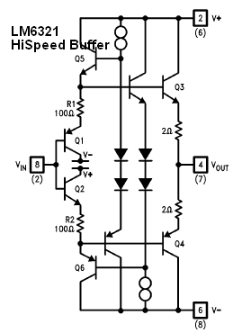
rjmHere is LM6321 HiSpeed Buffer
Has also 2 Ohm resistors.
R1, R2, 100 Ohm are used to set bias current in output.
Have you seen this post?
0.010% THD is not impressive for a buffer stage.
It is not bad. But it is higher than it could be.
If you run output stage in true Class A.
I get .01% for 1 Vrms into 15 ohms.
Walt Jung's circuit managed .01% for 1 Vrms into 150 ohms.
I'm pushing ten times as much output current, and ten times the output power, for the same distortion.
As presently configured, the class A output power is less than I planned, only 1 mW into 16 ohms, because the board layout doesn't thermally couple the driver and output transistors. This will be addressed in the next revision, but the measured performance of the prototype version is sufficiently good that I will give it a full listening evaluation before proceeding.
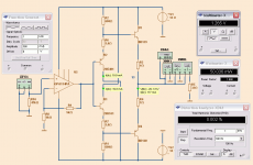
Here is a buffer that gives THD 0.002% into 32 Ohm at 50mW open loop.
It is Class A with plenty of current.
So in such a circuit, to get like 0.010% or lower dist we have to make bias very heavy.
Here it is 117mA.
Colsed loop shows very little THD, of course.
It is Class A with plenty of current.
So in such a circuit, to get like 0.010% or lower dist we have to make bias very heavy.
Here it is 117mA.
Colsed loop shows very little THD, of course.
Attachments
As I recall you use BD135/136.Are those are your simulations? If so could you change the values slightly to match my circuit and compare? I'd like to know how close the simulation comes to the measured result.
Thanks-
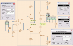
I use +10.8/-10.8 Volt supply
Resistors: 340, 0.25 Ohm
I get much higher THD.
So, in this case it is no good simulation.
Attachments
Any thoughts as to why the simulated distortion is higher than in the real circuit?
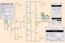
The only difference is I was using a 47 ohm in series with the 15 ohm test load. So while the output current was the same, the transistor voltage swing in my case was 4.1x higher. That and I had 1 ohm for the output emitter resistors at that time.
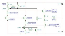
The 29 mA bias through the driver transistors is exactly as expected. So far so good. The bias current through the output transistors is showing 37.8 mA, which is odd because R3 and R4 reduce the Vbe of the output transistors by almost 10 mV compared to the driver transistors, so the current should be about 20-25 mA not 37.8 mA.
Unless the simulation tries to account for the output transistors heating up from the output current? That is the only explanation I can think of...
Thanks by the way for doing that for me. I tried modelling the buffer in ltspice, but it gives me no reliable information.
The only difference is I was using a 47 ohm in series with the 15 ohm test load. So while the output current was the same, the transistor voltage swing in my case was 4.1x higher. That and I had 1 ohm for the output emitter resistors at that time.
The 29 mA bias through the driver transistors is exactly as expected. So far so good. The bias current through the output transistors is showing 37.8 mA, which is odd because R3 and R4 reduce the Vbe of the output transistors by almost 10 mV compared to the driver transistors, so the current should be about 20-25 mA not 37.8 mA.
Unless the simulation tries to account for the output transistors heating up from the output current? That is the only explanation I can think of...
Thanks by the way for doing that for me. I tried modelling the buffer in ltspice, but it gives me no reliable information.
Last edited:
The simulated distortion is much lower than in real life.
The simulation gives ~0.12% THD for 1 V rms into 15 ohms. I measured an estimated ~0.01% THD for 1 V rms into 15 ohms. The simulation returns the higher value.
Please read the previous posts carefully before commenting.
Returning to the matter at hand:
One consideration of class B output stages is the large amount of heat dissipated in the output transistors when applying a small signal to a low impedance load.
Consider: 66 mW into 15 ohms is 1 V rms and 66 mA. For +/-10V supplies, the output devices dissipate 9 V x 66 mA or 564 mW! (Probably: it's still too early in the morning right now for math.) It's curious though, that for class B and a constant load current, that the heat in the output devices decreases as the output impedance increases, even though the output power increases.
Which is a roundabout way of saying that class B amps are horribly inefficient when the output voltages are much lower than the supplies. Low efficiency per se. is not such a big deal, but the large amount of transient heat might well be.
Perhaps my adding the 47 ohm output series resistance reduced distortion by lowering the thermal load on the transistors, or perhaps the simulation over estimates the effect?
Lineup: try running the simulation at 0.2 Vrms output rather than 1 Vrms, this will put the output in Class A operation so the distortion figures should suddenly improve dramatically.
Last edited:
I would not bother much with simulating distortion. A heat sink is required.
This circuit of yours require a little more than a heatsink to make
it functionnal, if ever it is possible...
Right. The same applies to Sziklai outputs as well. Class A operation is to be striven for.However, the distortion rockets when you apply gain and the outputs enter AB.
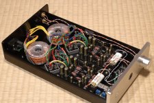
Hi guys. I'm listening to my new amp right now. It sounds fantastic.
I agree that class-A is what you want here. That was my idea from the beginning, sorry I guess that got lost when I posted the distortion measurements. I was trying to say "even well beyond class-A operation the distortion is only 0.01%, so as long as we keep in class-A we are rockin'!". I was not trying to imply that 1 V rms into 15 ohms was an operating point I was aspiring to achieve.
I disagree, on principle, that the buffer should be inside the feedback loop. I haven't done a comparison though. I've left it outside and this gives me exactly the sound I was hoping for, so as far as I'm concerned that's that. The boards are switchable if anyone wants to experiment however.
Attachments
- Status
- This old topic is closed. If you want to reopen this topic, contact a moderator using the "Report Post" button.
- Home
- Amplifiers
- Solid State
- Diamond Buffer Emitter Resistor Question