30V at full load?
Are your toroids specified as 30V at full load? If not, and depending on their regulation, you may get well below 42 volts at full load. That is of course when your drivers need their maximum voltage, and you don't want the regulated Driver DC to drop out of regulation then.
I have a similar situation. Transformer specs are: 29.6V -0-29.6V at no load, 500 VA. I get 42VDC at no load (and light loads), but have not been able to check at full load (huge resistors needed!). That is the question - what will the DC supply be at full load. One has to go down 3 volts from there on the zeners for the regulator; or may it be less than 3 volts?
Does anyone have experience with the minimum voltage differential before the driver regulators drop out of regulation? I suppose it could be calculated, but I don't know how.
Francois
meanman1964 said:Nordic thanks,now I can use my 30 V toroids.
Are your toroids specified as 30V at full load? If not, and depending on their regulation, you may get well below 42 volts at full load. That is of course when your drivers need their maximum voltage, and you don't want the regulated Driver DC to drop out of regulation then.
I have a similar situation. Transformer specs are: 29.6V -0-29.6V at no load, 500 VA. I get 42VDC at no load (and light loads), but have not been able to check at full load (huge resistors needed!). That is the question - what will the DC supply be at full load. One has to go down 3 volts from there on the zeners for the regulator; or may it be less than 3 volts?
Does anyone have experience with the minimum voltage differential before the driver regulators drop out of regulation? I suppose it could be calculated, but I don't know how.
Francois
After you have your supply assembled, measure the DC voltage without load
and adjust the series of zener diodes to have 5 volts less into the input circuits.
Good idea is to measure the supply under load... 2 amperes each rail for instance..using resistances to drain power into each rail simultaneously to check the supply behavior under load conditions....then you will know the real thing, and will adjust zener properly to have excelent sonics.
Of course, if you perceive your supply as too much weak, than adjust your zeners to loose more than 5 volts, as will depends from your losses into the supply.
The idea is to have swing of voltage into the power transistor colectors, but not to have swing of voltage into the bootstrapp and into the input differential... stability of voltage there is important to quality.
Also, this reduces your voltage swing into the output...the rail regulators, despite very good for sonics, also "eat" a lot of voltage swing into the output, and this means power losses.
Compromise.... this is something that is up to you dear builder.
Removing the series transistor you will have a lot of power...and sound quality will go down....but this is very optional.
There are supplies that you measure 42 volts while nothing is connected into the supply output wires, so, unloaded.... and this same supply can go down to 37 volts when you adjust your amplifier to drain 100 miliamps each rail....so.... we use to say it is a 42 volts supply, when in the reality it is a 30 volts supply or even less than that.... during hard work voltage will go down.
This must be observed, and measured during operation over 4 ohms, and this is needed to adjust correctly your zener diodes to maintain the input circuitry with stable voltage..... series regulation alike the one we are using, that has not error amplifier, cannot result very stable.... and in special, no supply is able to keep stable 35 volts, for instance, while the input voltage reduces to 30 during power peaks.
Circuit was made considering decent supply (150 watts minimum, real power from the supply to each channel, as HRII will provide 35W RMS undistorted over 8 ohms and maximum of 70 watts RMS over 4 ohms)... and decent supply will not go bellow 32 volts during normal volume operation.
We can have..and i have one transformer that way in my home, tha produces 45 volts and when i use it hard the voltage goes to 33 volts...so.... this one will not be good to use with that kind of rail regulators....as i can adjust the input circuit voltage to 40 volts and the supply will go to 33 volts and will produce a big mess.
regards,
Carlos
Attachments
meanman1964 said:My 30 Volt toroids give without load and input of 230VAC 32 a 33 VAC if that is what you mean?
Uncle Charlie explained the situation very well, and it is probably best to test the power supply voltage under the load you plan to run it. But if you get 32-33VAC with no load on your "30VAC" transformers I guess that your transformers are specified 30VAC at some unknown load.
If you are a bit lazy like me you could just build it and try it. The worst that could happen (I think) is that you may have to reduce the voltage regulator zeners a bit if you don't like the clipping behaviour of your amp.
Francois
The amplifier can work into a very wide range of voltages
You can have 35, or 39 or even 42 volts without the need to make big modifications.
The first one, to think about are the electrolitic condensers insulating voltage.
The second one, when you are near 50 volts, are the transistors you will use, bigger voltage transistors will be needed, alike 2SC4793 and 2SA1837 into drivers position....and 2SC4793 into the VAS master position.
Why those ones when thousands may work fine there?
- "Because those ones are very good in performance, reasonable low capacitance, good gain, high voltage, reasonable power, made of insulating material into the case, so, you do not need insulators on them to place them into heatsinks and the cost is very low..they are cheap and good units"
There are thousands of other ones may work, some of them may oscilate.... for instance, MJ15032 may need adjustment into the Miller compensation capacitor.
The other modification is to change the zener diodes to have 3, 4 or 5 volts less into the input circuits...and this will be a decision you will have to make depending the confidence you have into your supply......if good supply you can adjust to 2 or 3 volts less than the main supply voltage (to the power transistors, the rigth supply, the non regulated supply)...if your transformer is not good..then you may reduce even more than 5 volts not to have fluctuations of voltage into the input.... this is very important, because means quality of audio reproduction, means total absence of supply modulations into the audio.
You may say:
But good designers, famous ones, do not use rail regulators into their designs?
- "Yep, and observe they use class A, and class A already have a constant current that keep the supply voltage much more stable than the AB amplifiers.... this makes sittuation less dangerous to the sensitive amplifier stages....others, that produces AB designs do not use..because.....heheh...ask them their reasons!"
The HRII can work, even with 63 volts, but in this case you will need to include more 2 pairs into the output, to replace VAS and drivers transistors, to increase all the condensers voltage, the capacitors voltage,and the resistance that feed the zener..from 2K2 you may go to 3K9 if 50 volts and 4K7 if 63 volts.
Remember also, that each output transistors will need its own emitter resistance (0.47 ohms or 0.33 ohms, and this to equalize the power over the transistors, as they have different gains normally) and their own base stopper resistances too.
I think the increasing of voltage into the HRII is not something very good, as you have bigger voltage option that is the Precision 1....so.... better to go to this one that has room into the board to more output transistors.
Never forget, if not using speaker protection (by Nordic) use fuses... one for the positive rail, other to the negative rail and the third (important) to the speaker.
Why to use into the speaker?
There are failures the burns one of the rail transistors only, this means voltage into the output...this may burn speaker..so....do not forget the speaker fuse..... a good idea is to use lower value into the speaker fuse, as audio result more average than peak into the fuse..... it is burned by long time surges of current, not fast devices...so.... if you will operate full power into 4 ohms.... and that means 4 amperes of current (2 amperes into 8 ohms) ..then you can use 3 amperes and 1.5 amperes fuse in series with the speaker.
Of course, to work with this amplifier, the speaker must hold 4 amperes if 4 ohms and 2 amperes if 8 ohms....the speaker must be able to 70 and 35 watts RMS... the problem you may face is that speakers are specified for marketing purposes.... not a decent marketing i think....you may see your 100 watts speaker going to the maximum mechanic movement with 8 volts...so.... real audio is 8 watts if the speaker is 8 ohms... and you may see it specified as 100 watts..... i do not think those speaker coils can hold that power if they are sensitive to small power....those ones, have their coils melted even using fuses...not because fuses are very bad (they are not VERY bad, only a little big bad) but because speaker was weak.
This makes many folks not to appreciate fuses, and this is more a result of their bad decisions related fuses dimensions or speaker selections... also some of them do not like fuses into the speaker output line.....ahahahaha..... bad luck to those ones.... because speakers do not like supply voltage into their own coils too.
We use, I DO, and i think many folks do the same, to blame designers, amplifiers, speakers and fuses...but observe those things are all controled by ourselves...our ignorance, inexperience is the correct thing to be blamed....as we decide, and sometimes we decide wrong.
Other thing...condensers use to react against voltage variations...opposes to voltage variations..condensers are stock of electrons that feed energy into the moments voltage goes down.... you see this may be good sometimes and may create some problems too.... do not use big condensers into the amplifier, some experienced folks perceived sound mufled because of them... do that only when needed, when you do not have electronic regulation into the rails, when you have resistances into the rail or when you have nothing in series into the rail... as supply auxiliary capacitance or to compensate the cable length from the supply to the amplifier board (when this is too much long, say..bigger than 15 inches)...or when you have power consumption into the input circuits..special circuits that drains several miliamperes.
Relay protection are good, but also can create problems...when you open an electrical circuit while current is crossing you have "arcs" of induced current that may burn output transistors...say..if operating full power and current sensor activates the switch off protective function, and 100 volts peak to peak will be crossing relay contacts..hehehehe...you may induce higher voltage that may burn the output transistors.... they are better than fuses, but subjected to problems too, in special while high power voltages are present...also they have electrical contacts, that need to hold good power....so.... Nordic protection is very good as he had analised all those aspects.
regards,
Carlos
Carlos,
The best thing to do is stick by the schematics voltage.
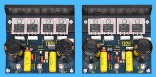
I've a special regulated supply for audio amps from Thel Audio in Germany.
www.thel.de
It's written in German but if you want I try to translate it for you.The reason I bought this was to avoid the problem of buying toroids for each amp I shall make.With this I could make the voltage I need positive or negative or both.
The best thing to do is stick by the schematics voltage.
I've a special regulated supply for audio amps from Thel Audio in Germany.
www.thel.de
It's written in German but if you want I try to translate it for you.The reason I bought this was to avoid the problem of buying toroids for each amp I shall make.With this I could make the voltage I need positive or negative or both.
Attachments
Germans are very clever... i have strong appreciation about them
They have clever solutions into everything they do.
I have some fear about them too...because recent Hystory, but i can dennie they are great.
And no good to say they are good, as problems starts when they perceive they are special.
Good solution my dear.... variable voltage supply can feed many different amplifiers, also clever, as it is very stupid to have 5 supplies to 5 different amplifiers we build...and we do not listen them at same time...so....more clever is to adjust your supply and use amplifier A, and them the amplifier B and so on.
I feel happy when i see people using the brain.... everybody has, but only few put them to work.
I have friends, despite clever folks, intelligent folks, that switch brain off almost all the time.
If you suggest them to build another amplifier they start to complain that have not another 35 volts supply when they have already one amplifier assembled that has that supply inside...they need just to solder 3 wires and run those wires into the new circuit they are assembling...but people do not think on that...or are bad in brain flexibility..they say.
-" No!..that supply is for amplifier A, not for both of them!"
By the way... i love languages ...and "Eingang" and "Ausgang" is beautifull!
ahahahahahah!
regards,
Carlos
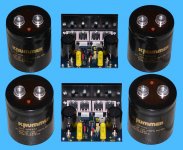
Just some notes... the capcitor spaces on the board, can easily carry 100V caps..
Also related to the size of caps (capacitance), although I know the source or person the comment was attributed to , and have very few people I respect more in this line of things....
My experience, was that the big caps I used, increased details in the mid and top range if anything...
Doing AB test.. the sansui sounds muffled in comparison and even the DX classic. I do also believe (and eperienced) that some electrolytics jsut do not belong in audio circuits, and this is not price dependant, had some realy nice sounding cheapies...
The units on my boards at the moment are Panasonic TSUP caps. at 2 x 10000 and a cheap, but clear sounding 4700 on the input side... considering the little current useage of the input side, the 4700uF caps are undoubtably overkill and a sign of my inexperience at the time... I do however like a cap that has a ripple current rateing exceeding the maximum instantanious potential current draw of whatever it is connected to...
Bottomline is if you got something you think will fit the holes and voltage requirements... give it a shot. Worst case scenario, you swap those parts later on... if your HRII sounds muffled in any way, I suspect something is very wrong... It is one of the clearest sounding amps I have heard. And even giving acceptable sound through a set of test speakers that makes jsut about any amp sound like fog horn.
So for the input cap 2200µF can be enough but take a good one.Nordic said:
The units on my boards at the moment are Panasonic TSUP caps. at 2 x 10000 and a cheap, but clear sounding 4700 on the input side... considering the little current useage of the input side, the 4700uF caps are undoubtably overkill and a sign of my inexperience at the time... I do however like a cap that has a ripple current rateing exceeding the maximum instantanious potential current draw of whatever it is connected to...
Do you mean the The ones at C2 and C22 o the board? they can in fact be as low as 470uF, but try the ones you have... and see what results you get
Input cap normaly is the name of the cap on the positve input signal line... just want to avoid confusion...
The value for the input cap should optimaly be between 5.6uF and maybe 10uF if you realy want to have an overload of bass. Mine are 6u8. It is marked as 2u2 on the board, which is the only "error" that made it through due to misunderstanding... a relic form the DX amp. Will still work with 2u2 but the bass roll off will be earlier.
Nordic said:Sorry, man, I looked at the bypass cap's number...
look between the holes for c1, 2 9 and 10...
There are alleady holes for mounting bypass caps there, provided of course you use caps that fit the clip on holes.... otherwise just solder them to the bottom over the pins.
Yes I know but can it be by using good bypass caps that the sound can changes in the positive way?
I think, not as much as the guys running "boutique" parts shop would claim... I think you can get a bunch of "flavours" by just getting a handfull of diffirent elcos from 470u to say in theory 4700uf.
There are probably as many arguments for bypasing as there is against... I say its cheap enough to buy a handfull of spare caps and find what suits you.
You wouldn't send someone else to go choose icecream for you anymore than you should want anyone stamping their view on what is best sound-wise.
You will normally find the bigger the price on their last receipt, the more truthfull they proclaim the benifits of installing brand new screws made of crabshell or something like that.
When I built chipamps I was always awatre how much better they sounded with more acceptable quality components (something that actualy had a half decent datasheet)... As I started building te DX range, I have become more immune to that.
They sound good, almost regardless what you throw at them.
- Status
- This old topic is closed. If you want to reopen this topic, contact a moderator using the "Report Post" button.
- Home
- Group Buys
- Destroyer x Amplifier DX HDII version.