Re: I have made a post because of you Gaetan.... i hope you had time to read
Hello
I did read it Carlos, and I saved it on my computer HD.
Thank
Gaetan
destroyer X said:This is the post i have made was for you Gaetan...not only for you, but also because of you.
http://www.diyaudio.com/forums/showthread.php?postid=1208199#post1208199
regards,
Carlos
Hello
I did read it Carlos, and I saved it on my computer HD.
Thank
Gaetan
i see that thread is progressing ...
well, nice....
also the idea of having it pure - without modifications made in this thread is good if Carlos wants this way....this will keep people clear what to do - unfortunatelly this thread is extremely big for people to read - so it is perfect to have the entire sch, boards, explanation stuff on Greg's page where everything is concentrated and people that do not have time to read everything can look there and find everything they need....
nice..
Yes Sparkle... I am learning how to conduct a thread
This was a very good experience to me...that too much freedom may turn a big mess...or at least, a confusion.... we have to work alike diodes....to go cutting the peaks!
If, in the future, i decide to open a new thread..that one will have not those errors and will work fine...i am sure about that... i have learned a lot.
Greg Erskine had not so big problems, as he is very organized and sistematic.... he used to check things twice and was extremelly helpfull to me..and will continue to be during this new "arrangements" we are discussing those last days.
Excesses of informations turns people afraid of the amplifier....not a very good idea....three constructors having circuits finished and working, and one guy fixing his circuit, is not a so good result for a thread that has monthes since the early beginning...and having more than 50K hits...there are others doing, some of them in secret.... and those ones, not informing the problems they are facing... produces concerns in my mind.
Some small stones in the middle of the way are beeing removed, as a result of hard work and constant attention to the thread...now, deviation from the North, are beeing slowly beeing corrected.
The resistances to bias were not a good idea...they need enormous heatsinks and fan blowers as they do not compensate temperature increasings...this was stupid...i have to tell frankly that..because is oposite to the idea of cheap amplifier...also...how big is that heatsink is hard to be realised by beginners.
Now we are fine tuning...and finally the thread will march with a perfect harmony.
regards,
Carlos
Folks...Greg had thermal runnaway..the same as Klaas had.
So....my conclusion is that i was extremelly lucky with my enormous heatsink and my bias point.
Greg found stable using 32 volts and a very small bias....things turns under control.
Using standard bias, using his heatsink in the back panel, using his ceramic insulator, and nominal voltage he had a fuse burned...was replaced and the equipment returned to work fine...was only the fuse.
Also Greg found that the heatsink was not too much hot when the transistor case was very hot!...this is really the thermal runnaway...and this way, despite my tests had shown me the opposite (better heat transfer i had..enormous and good heat transference ratio aluminium heatsink..sanded transistor bottom and i have used mica insulators...Greg used ceramic.)
Also my unit was underbiased near the minimum limit were the sound were not distorting playing very low level music...also my heatsinks were in the perfect convection position...Greg is not using the perfect convection position too.
And i have used fan, as i was testing full power for 1 hour long.
Under that sittuation....i had not problems....under other sittuations Greg had and Klaas had...and this is more than enougth.
" Resistance in series with trimpot, to biasing adjustment are not an option to the Dx amplifier anymore "
Mr Greg will correct those things.....my errors, into the web page, and we gonna march for the future, more confident, as we could superate this error in advance related constructors (the ones constructed used VBE multiplier because of my suggestion...i was afraid of their heatsink size..but the problem was bigger than heatsink size..including much more variables than the ones i was taking into account)
Be happy, as using VBE multiplier, Dx amplifier is "rock stable".
Enjoy!.....now more tested than ever.... more reliable than ever.
Also transistor options will not be suggested anymore.... Dx amplifier will guaranteed as plug and play, only, when using the suggested transistors posted into the home page..the ones printed into the schematic.
regards,
Carlos
Inex..have you made a break into debug your amplifier.
I will be happy to obtain some news from you.
If you prefer, and feel more confortable, you can come to my personal E mail adress.
panzertoo@yahoo.com
regards,
Carlos
.....................................................................................................
Peace for all folks and all families from every country and every religion!
In my place, and others around the world, it is a Mother's day.
I wish long and healthy life for your mothers folks...and that you enjoy her presence, not only today, but for all days in your life.
Nothing is more important than our mothers..absolutelly nothing!
They are the one that will love you even if you turn someone alike Bin Laden...her mother thinks he is lovely and sweet.
Of course, none of us agree.
regards,
Carlos
I have serious reservations abouth those thick white plugs you guys use as insulators... my Transistors, came with paperthin seethrough crystal like insulators..for free... guess its mica or something...
I just fail to see how heat can get through those thick white things effectively... put it this way... if i wanted to feel if something is hot and I put those on my fingertip first, I would probably have to wait a while to feel the heat....
I don't see why transistors should be any diffirent from CPUs, on which the best is to use an almost seethrough thin layer of thermal paste... Unless you have non aluminium heatsinks in which case you can use liquid metal, which has thermal transfer a couple of times higher than even the better pastes for computer use... Remeber those babies dissipate up to hundreds of watts, and only have a small heat transfer area, and just as small little heatsink...comparitively.
I also dislike those ceramic parts...they delay to transfer.
And because of that, thermal transference is smaller..as the internal transistor may reach very high temperature while is waiting the ceramics to take that heat and them transfer to aluminium.
I have faced those problems in Radio Frequency transmitters, were i used to replace those ceramics insulators by standard mica insulators...not so pretty, also not so fashion..but transfer heat better and faster.
When you touch transistor cover and it is more hot than the heatsink this seems that something is wrong...two main options may happens:
Or you are using much more power than the unit can hold
Or it is not transfering the heat to the heatsink..
Well..those things are measurable.
But the process is not complicated..the transistor gain heat..if do not have good heat transference..that is speed and capacity...it turns more hot....when it turns more hot, the junction resistance is reduced.... with a reduced resistance you will have more current crossing....more current crossing will produce more heat....more heat will turn the transistor more and more hot...beeing more and more hot, its junctions resistance turns smaller and smaller...current crossing will be bigger and bigger...and than the transistor will be hotter and hotter...this goes till the destruction....or.... a burned fuse will interrupt this process.
And what started all that thing?
The heat transference...without heat...no problems!
I do not blame those ceramics insulators, but i felt that i had the need to introduce some thermal control using diodes and VBE..as people can use those things (as small and bad positioned heatsinks) and resistances will not compensate..unless you use "NTC, negative thermal coeficient"..those old resistances sensitive to heat that reduce their resistance when receiving heat....well...this i not easy to find anymore, also not cheap, also not simple.
The result of that is that i had to find other more safe options..this way people can use those insulator, can place heatsinks inside case, can mount in wrong position, can use smaller heatsinks than the needed ones, can operate with steady tone, square wave and use the amplifier under the sunligth....well....the amplifier will turn "hard to kill"...and this is much better.
I had made many modifications into CB transceivers, from the seventies to the eigthies...and i use to double the power...those ceramic insulators were the first ones to be removed and replaced by mica....but this is my experience..people thinks that ceramic, because white, because clean , because pretty and because expensive is better...no!..they are not better!..they are worst!
I have made some modifications keeping the original ceramic insulator...radio returned burned or with leakages in the output, and many of them returned with their output transistors without gain...they lost gain...gain fall down from 23 to gain 1.
I had not those problems using thermal compound, sanding transistor back and using very thin mica insulators...but those things are less pretty...and beauty is something important to some folks.....ahahaha..some of them end making a marriage with a "trouble pretty woman"
Of course beauty is important...but really not too much.
regards,
Carlos
Attachments

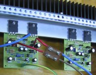
I guess it might be usefull to attach the vbe with the same screw as one of the transistors, thus clamping it to the transistor body, for closer tracking...
I can confirm my transistors ran cooler than the sink, at least it felt that way...I extended my PCB to cover the transistors up to the hole... to create a capillary chimney (boards mounted to the sides).
I still think it almost doesn't matter how big your sinks are without efficient transfer to it.
PS greg, your programable relay controler board exposed fine today... noticed I need drillbits, but I'll get those tommorrow when I get the 1/8W resistors for it... allready found resistor network IC for the button port...")
Also news on Tina, I found a copy that works and a tutorial...
I can confirm my transistors ran cooler than the sink, at least it felt that way...I extended my PCB to cover the transistors up to the hole... to create a capillary chimney (boards mounted to the sides).
I still think it almost doesn't matter how big your sinks are without efficient transfer to it.
PS greg, your programable relay controler board exposed fine today... noticed I need drillbits, but I'll get those tommorrow when I get the 1/8W resistors for it... allready found resistor network IC for the button port...
Also news on Tina, I found a copy that works and a tutorial...
Carlos,
Your prolific writing style is fun to read. But there is a lot to read now. I think for a while you had the link to Greg's Dx site in your tag line. You should leave it there and put it in your profile so that new readers of the thread can quickly find it.
Sheldon
Your prolific writing style is fun to read. But there is a lot to read now. I think for a while you had the link to Greg's Dx site in your tag line. You should leave it there and put it in your profile so that new readers of the thread can quickly find it.
Sheldon
Yes Sheldon..thanks...i will do it.
Inex
Do not worry and be happy...this happens with everybody..you are not the first or the last to burn things.
May someone with courage to tell this clearly to us.
Congratulations be the courage...you mom may be proud of you.
regards,
Carlos
Inex
Do not worry and be happy...this happens with everybody..you are not the first or the last to burn things.
May someone with courage to tell this clearly to us.
Congratulations be the courage...you mom may be proud of you.
regards,
Carlos
Another Dx Amp up and Running
Hi Guys
Sorry for the delay but my internet at home is giving me problems. I completed my first Dx amp on Friday night. Did some last checks and switched it on. Believe it or not.....my Dx amp worked the first time. I ajusted the bias current to less then 3mA and connected my speaker and source. ALL HAIL TO CARLOS. This amp is well designed and the sound is clear....clear....clear. I was amazed by the sound quality of this amp. The bass,mid and high is very well balanced. I han no problem with the construction of this amp. Thanks Greg, good PCB layout. I am busy with my 2nd channel and will paste some pictures when I am finished. My amp is working fine without the Vbe multiplier and I have no thermal problems. I tested it at full power for about a hour (hope my neighbour still likes me) on Friday night with no problems. The amp is running cool. ALL HAIL TO CARLOS. I even compared this amp to my LM3886 Gainclone amp and sorry to say this, but the Dx AmP sounds much better and the sound is much clearer. Sorry gainclone fans. I will definitly build the bigger version of this amp after this. Anyone with a PCB layout yet for the bigger version ±56V DC???
Thanks again to Carlos for this amp. To all you DIY guys out there. build this amp and listed to the sound quality. You will not be sorry.
Thanks
Macd
Thank you Macd...but please my friend, include the VBE multiplier...it is much more
safe.
As i could see in two friends.... the thermal runnaway goes fast and we have not time to shut the unit off.
If fuses fail...them....booom!
Of course, using very big heatsinks and fan blowers you will never have those problems...depends also the insulators too.
Also, please, increase your bias.... use, at least, 35 miliamps as minimum.... with less than that, there are the danger to have output transistors off during stand by period.
If your bias measurements were not perfect you may have even better sound.
thanks by your informs.... made me happy.... and your happiness and enthusiam made be happy twice.
Also my agreement related gainclone...i made those testings here and i perceived exactly the same...Nordic too.
56V units were not tested yet.
Congratulations.
regards,
Carlos
Attachments

- Status
- Not open for further replies.
- Home
- Amplifiers
- Solid State
- Destroyer x Amplifier...Dx amp...my amplifier