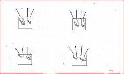
Forever13 said:Hi Andrew - I've drawn a layout to show what I'd had planned before posting earlier (and no doubt causing alarm!). I've tried to read up on this, and it was only seeing that post on another forum that got me thinking about the centre taps. Isn't this layout right? (earth being a bare metal connection to the chassis that's also shared by the PSU ground, amp power & signal grounds and ground for the speaker output?)
I assume you mean the other way round, Brown live and Blue neutral?(sorry, couldn't help that one)
Thanks again for your help and patience on this.
----------
Hi Carlos - I'll certainly find someone local to help me out before frying myself, the cat, the house, next door...
Hi Forever13,
I can't follow your schematic or follow your wording 100% but the schematic looks very wrong and dangerous to me, please delete it.
There is NO connection between the primaries and earth.
regards
Hi Forever,
hold off connecting the secondaries.
bring all four secondary wires to a 4bay terminal strip.
Just do the mains side first and power it up through the tester.
When you report back on powering the transformer only, we can safely lead you through the next stage.
hold off connecting the secondaries.
bring all four secondary wires to a 4bay terminal strip.
Just do the mains side first and power it up through the tester.
When you report back on powering the transformer only, we can safely lead you through the next stage.
Thanks guys - glad I asked rather than doddering on myself, could have been nasty.
Carlos - thanks ever so much, I'll be in touch later today.
Greg - will do - it's now gone, and thanks for the no-nonsense warning. I'll get advice from someone locally on this now.
Andrew - as above, I'll hold off doing anything else with the power until I get some first-hand assistance.
Carlos - thanks ever so much, I'll be in touch later today.
Greg - will do - it's now gone, and thanks for the no-nonsense warning. I'll get advice from someone locally on this now.
Andrew - as above, I'll hold off doing anything else with the power until I get some first-hand assistance.

Hi Carlos
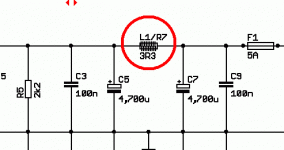
I was thinking about inductor (output coil) and resistor in amplifier before speaker not in psu.
I found in instruction resistor was 10ohm (but I didnt see wha wattage) and inductor 2uH (27turns of 0,6mm cooper). I asked does is wounded in one or two layer. If it is 1/2W (who is long about 10mm) only 16 turns can be on resistor body. If resistor is higher value it can be in one layer.
Thanks
Duka
All rigth dear Duka...now i understood....good!
Use the bigger resistance you can find.... 3 watts units here in brazil are good enougth...they have almost 8 milimeters diameter and 25 milimeters long... try 1 milimeter wire and produce your windings..... do the best you can, the bigger you can.... turn the most you can...the turns will be possible to wind up.
This is not critical... the internal resistance is to turn wide the operation to reduce the coil "Q"... increase the resistance value if you windings are smaller than the suggested...but...do not worry and be happy.
Dx Amplifier is a happy amplifier.... stable, reliable, and use only "good fat healthy and kind electrons"
Ahahahhahah! (LOL!)
Even if you make it ugly, double layer and a pig work alike mine...i ensure you electrons have not problems with that and they will flow without be bothered because ugly.
regards,
Carlos
Attachments
Hi Carlos
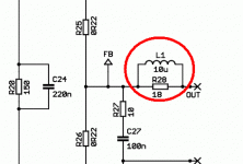
Thanks for reply. I understand but why different amps have different value. I am learning and I need some information about building. DX, some Bryston have 3uH, Quad 405 I think 3uH and a couple amps different coil. I think Quad have coil on ferrite.
One more time thanks
Duka
Thanks for reply. I understand but why different amps have different value. I am learning and I need some information about building. DX, some Bryston have 3uH, Quad 405 I think 3uH and a couple amps different coil. I think Quad have coil on ferrite.
One more time thanks
Duka
Please, do not use ferrite..it saturates and sounds strange
The peaks comes together a "Tac!" sound.... or a tic..in the reality is alike a drop out...sometimes it saturates and changes the signal.
The best is air core and heavy gauge wires...but they are big and ugly..also using resistances in parallel we change the coil "Q"... the bandwidth is changed.
regards,
Carlos
It was mistake DX and Bryston have 2uH .
After all I am know really confused. What to build?
Coil over resistor, or stand alone, 0,6mm or 1mm.
Your knowlage is higher than mine and you are i better solution.
Too, I havent meter for inductanse measuring and it is harder.
In any case, thanks
Duka
After all I am know really confused. What to build?
Coil over resistor, or stand alone, 0,6mm or 1mm.
Your knowlage is higher than mine and you are i better solution.
Too, I havent meter for inductanse measuring and it is harder.
In any case, thanks
Duka
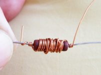
by DX :but they are big and ugly
Why ,they don't have to be
.Use the butt end of sharpie or cap...
An externally hosted image should be here but it was not working when we last tested it.
That one above is 2.3uH/10ohm 10turns 1.5mm which according to
self is the minimum needed to stop ringing and keep
the "fat electrons" flowin'(no effect on sound.
He experimented with 6uh (big
and ugly) and found no added advantage for one that big.
OS
- Status
- Not open for further replies.
- Home
- Amplifiers
- Solid State
- Destroyer x Amplifier...Dx amp...my amplifier