I will wait the darkness from the nigth, because i have perceived that without
visual stimulum i can concentrate myself better.
Also i will have my daugther to operate the reverse switch.
I do not trust in me for those things...well...humans has the tendence to pre decide the result they want...so... for me, because the hard work...the optimum result is to prefer the supply.
But i want, and need, to be scientific and fair.
So...will be listening those next 14 hours...and i suppose i will conclude.
Will create moments of silent...because brain adjust.
I prefer to perceive listening... theories says that supplies are not good..or...that they need to be faster than amplifiers to result fine.
regards,
Carlos
Attachments

Well...my mail box is overflowing because of friends sending me mails
All them telling me the same:
-"Regulators have to be faster than the amplifier to have transient response."
All rigth boys...but i am not using regulator because of transient... i am using regulator because my transformer is not holding the voltage when heavily loaded.
Also...because of transient..we can use the regulated supply...and into the regulated supply output we can install 22000uf each rail...so..we gonna have electrons for those transients (I suppose)
The idea, not only for sonic purposes....mine is for practical purposes too.
Of course, because of the Dx Precision amplifier, i need to know if those transients will be eated or not... and i have to think about costs...those condensers into the supply output makes me think
May be better to use them into the conventional, standard, common rectifiers and condensers supply.
I will check this listening... i think it will be the better way.
But will not be easy....it is sounding almost the same...but the next hours will give me more informs.
Daugther will operate the switch.
Also she will help..she had no preference..so...her evaluation counts.
regards,
Carlos
6 hours and four children latter i have an idea.
Absolutelly no difference...with electronic regulation or without, the girls perceive absolutelly nothing.
I also could not perceive.... a little bit more power without regulator..because the supply voltage is 56.5... when regulator was adjusted into 50 volts.... dinamic power only... feeling that had more bass.... and in the reality, had reproduced bass peaks with bigger voltage.
This biggest power is felt into the bass.... of course, exactly were we have the biggest power into the sound spectrum.
They start to distort almost the same power.... because the supply can loose some volts easy....bellow 50 the supply is more powerfull and you can increase power and it is difficult to go lower than 50.
The regulator have maintained the voltage also into 50....so... both sittuations had almost same voltage when the volume was up.
The electronic, adjustable circuit is still usefull when you have bigger supply voltages and you need to reduce it.. and keept it stable.
It is not bothering the sonics..also we could not perceive advantages.
regards,
Carlos
Hi Carlos,
If the amplifier is biased with say 50mA quiescent current at 55Vdc, then what is the quiescent current when output drive drops the rails to 48-50Vdc ?
This can affect reproduction quality during high power bursts where the loudspeaker system impedance momentarily fallss and draws the higher current which Andrew mentions.
I suppose the regulator will allow the quiescent bias to remain constant through peaks.
A zener in parallel with the bootstrap capacitor will also improve quiescent stability with rail fluctuation, without need for power regulation.
Cheers ............ Graham.
Graham Maynard said:Hi Carlos,
A zener in parallel with the bootstrap capacitor will also improve quiescent stability with rail fluctuation, without need for power regulation.
Cheers ............ Graham.
Hello Graham
Another interesting knowledge to learn for me....
I presume that the zener voltage are not same for most amp, so how do we calculate it ?
Let say as exemple, calculating the zener voltage for the DX standard.
Thank
Gaetan
Attachments
Hi Gaetan,
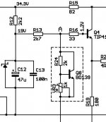
19V is shown across C12, so I would go for a 1W 18V or 20V zener.
If the rail voltage goes higher then excess low current through R12 will be shunted by the zener and lower half of the output stage, and not be allowed to increase the VAS current where it could modify the very highly sensitive 'A-B' output stage bias potential.
However for better output stage performance the R13 to R12 ratio may be increased so that R13 can be of higher value. This allows C12 to generate a higher impedance current source for the output stage.
For example R12 could be 1k and R13 3k9, which would give 27V at the junction of R12/13 and allow a 27V zener to be used.The value of C12 should always be such as to maintain bootstrap generation at LF, its load being R12//R13. If C12 has insufficient value, then a changing LF ripple develops in the bootstrap potential and this can modify output stage bias/distortion with dynamic audio.
If a bootstrap zener can be used then the amplifier bias could be set at the rail voltage equating to that of maximum PSU loading - where the transformer regulation losses and diode/capacitor drops are greatest - and then any increase in DC through R12 when the output stage is lightly run will be shunted away through the lower half of the output stage.
All theory. What would it sound like ?
Cheers ............. Graham.
Hi guys, I seem to be chaseing my tail in a circle...
I need some help...
Can one of you draw me a jig to match the input transistors at their in-circuit levels.... for the HRII
http://www.dxamp.com/images/DXHRII_amp_Sch_Ve.pdf
My previous attempt not working well...
I need some help...
Can one of you draw me a jig to match the input transistors at their in-circuit levels.... for the HRII
http://www.dxamp.com/images/DXHRII_amp_Sch_Ve.pdf
My previous attempt not working well...
Those low voltage Beta testers we have in simple multimeters works fine
Yes... they use low voltage...but gain 250 when measured with low voltage... 2 transistors found as 250 of gain into low voltage measurement also will measure the same under high voltage measurement...say...they will present the same result.
If under high voltage, for instance, as an example, the first one, measured 170 of gain...the second one will measure the same too.
Do not worry and be happy... also matching is good under 20 percent...not needed to find substitution of transistor when you find one with 170 and the other with 173.... this means "super matched ones!"
If you find those dual transistor in one single package and measure the internal transistors gain (this is possible and i use to do this) you will perceive something alike:
First one - 235
Second one - 249
This is matched!
regards,
Carlos

Hi,
search Anatech and find his matching for the AAK pcb
He is basically saying, make up a jig that matches the circuit arrangement of LTP pair but with the two bases connected together with a pair of 10k resistors.
The high value of base resistors requires a fairly close match for hFE but this is not necessary for the real amplifier. Preselecting for hFE helps with this.
If you need to measure hFE then high values of base resistor make this easier.
If you only need an approximation of hFE and are really looking for a match then lower value of base resistor works better. Try 1k0 instead of 10k.
IT IS MUCH MORE IMPORTANT TO MATCH Vbe @ operating current.
http://www.diyaudio.com/forums/show...452#post1316452
wire up an 8pin DIL socket
ecbe
ebce
with the top Es connected and the bottom Es connected.
This arrangement allows BC5xx and 2sa/sc to be inserted into the same jig and keep the flat faces towards each other for close thermal coupling. (if you go back a dozen posts, you'll find out why thermal coupling is so important).
MPSAxx and 2Nxxxx devices will be back to back and need a differently wired DIL socket to allow thermal coupling. (you could use a 14pin DIL socket wired to allow all four types to be placed face to face)
14pin wired as
ecbe,ebc
ebce,cbe
with the common connections in each row connected together.
Destroyer,
matching hFE only, is of little to no value for achieving balance in the emitter currents in the input LTP. Matched hFE achieves similar to same offset currents in the inverting and non-inverting inputs IF the emitter currents match in the operational circuit.
BUT, if the LTP is unbalanced then this is the same as saying that the emitter currents are different and this in turn makes the input offset currents different. This leads to the conclusion that different Vbe gives different emitter currents and even with precisely matched hFE will lead to different input offset currents and the result is output offset and worse offset that varies with temperature (=offset drift).
edit, I have swapped the 2n/MPSA with the 2sa/c and vice versa.
hi Nordic,
Nobody would be expected fully matched transistors for the price you are selling them. It is time consuming just matching for hfe because the heat from your fingers changes alters hfe.
Please don't wear yourself out !! People will match their own, if they think it is that important enough.
regards
Nobody would be expected fully matched transistors for the price you are selling them. It is time consuming just matching for hfe because the heat from your fingers changes alters hfe.
Please don't wear yourself out !! People will match their own, if they think it is that important enough.
regards
DC gain is an excelent reference to match transistors.
Of course fine matched will be more interesting than different ones.... but we have to take some care not to turn too much obsessive with those things... because waste time and put turns our hairs white very soon... also shortens the life time.
We can check every miliamp and produce graphics, to see the best point... from the first miliamp till the maximum, data sheet allowable, current...but really, factory already did that for us.
A reference.... some ratio from colector current versus base current is already good... and if they are almost the same to 1 miliamp... it will be almost the same at 10 miliamps too.
Those Dc testings are good enougth... so good enougth that is Universal... you can find them into almost all world wide multimeters.... and they are there because needed... as a reference.... of quality, and to matching purposes too... also they are transistor testers, as damaged ones will not measure correctly... will not measure or will be very different than your spectations.
Alternated current is not more than and oscilating, waving, fluctuating in amplitude DC voltage.
Also Dc or Dc voltage. is not more than an alternate voltage that give up to swing or is keept stable by an external force.
So.... Dc measurements are showing us the Ac qualities too... they have a ratio and are intimatelly connected one each other.
Be very carefull when searching for good transistors and matching them with the intention to have better sonics.... for instance... remove you cheap, and easy to find BC546 from some differential circuit (not Dx amp..it uses PNP..because higher gain..normally higher than his counterpart).... then you find matched 2SC2240.... those ones with 550 of gain, while the BC546 had 320 only.... than you replace the previous, former, BC546 form the circuit and solder the 2SC2240 in the place.... the result will be better....but NOT because you have now a better matching of gain..... the better result is because of better transistor...the 2SC2240 is a better transistor...but also easier to oscilate too.... you have advantage into one side of the story, and disavantage in the other side... compromise.
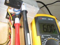
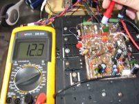
You see, the problem mismatch creates.... mine is mismatched...and sounding excelent... this prototype is hardly mismatched..but VBE are matched under 1 microvolt....you see the off set....not bothering sonics.... this represents 18 microwatts of power wasted... and will not confuse the amplifier...it will still operate fine with this off set.... this will not bite us!
See the image.
regards,
Carlos
Of course fine matched will be more interesting than different ones.... but we have to take some care not to turn too much obsessive with those things... because waste time and put turns our hairs white very soon... also shortens the life time.
We can check every miliamp and produce graphics, to see the best point... from the first miliamp till the maximum, data sheet allowable, current...but really, factory already did that for us.
A reference.... some ratio from colector current versus base current is already good... and if they are almost the same to 1 miliamp... it will be almost the same at 10 miliamps too.
Those Dc testings are good enougth... so good enougth that is Universal... you can find them into almost all world wide multimeters.... and they are there because needed... as a reference.... of quality, and to matching purposes too... also they are transistor testers, as damaged ones will not measure correctly... will not measure or will be very different than your spectations.
Alternated current is not more than and oscilating, waving, fluctuating in amplitude DC voltage.
Also Dc or Dc voltage. is not more than an alternate voltage that give up to swing or is keept stable by an external force.
So.... Dc measurements are showing us the Ac qualities too... they have a ratio and are intimatelly connected one each other.
Be very carefull when searching for good transistors and matching them with the intention to have better sonics.... for instance... remove you cheap, and easy to find BC546 from some differential circuit (not Dx amp..it uses PNP..because higher gain..normally higher than his counterpart).... then you find matched 2SC2240.... those ones with 550 of gain, while the BC546 had 320 only.... than you replace the previous, former, BC546 form the circuit and solder the 2SC2240 in the place.... the result will be better....but NOT because you have now a better matching of gain..... the better result is because of better transistor...the 2SC2240 is a better transistor...but also easier to oscilate too.... you have advantage into one side of the story, and disavantage in the other side... compromise.
You see, the problem mismatch creates.... mine is mismatched...and sounding excelent... this prototype is hardly mismatched..but VBE are matched under 1 microvolt....you see the off set....not bothering sonics.... this represents 18 microwatts of power wasted... and will not confuse the amplifier...it will still operate fine with this off set.... this will not bite us!
See the image.
regards,
Carlos
Attachments
Hi Andrew.
Yes indeed.
The Vbe potential as well as hfe need to be matched.
If those little input transistors are not supplied on ribbons, I stick them in line on tape myself. I then go along each individually and write the Vbe measured by my digital multimeter on the paper beneath each transistor.
It is essential that the transistors are left to settle at room temperature, away from sunlight, away from any heat source, and that they are not touched. (Only the tape should hold them in place while meter probes are applied.)
After measuring the Vbe, and writing the figure down, repeat the measurement - but - the meter probe which is in contact with the base lead should be made to touch the collector lead as well. This will give a reading lower than the Vbe because transistor conduction has been induced.
eg. Vbe = 580mV; V(b+c)e = 520mV.
The lower the second reading the higher the current gain of the device.
When all are measured you can pull away some which have the closest matching figures, and then compare these for match at circuit voltages and currents.
Those with different Vbe and V(b+c)e figures are likely to prove quite different in a real-world circuit.
Cheers ............ Graham.
Using Universally aproved methods, we can save time and waste it in other interesting
things.
I will drive this car today.... Jorge will come here soon.... will be very interesting to put it into a Highway and use my iron feet on it...ahahahaha.... 1965 automobile.... The Simca Chambord.
Made in Brazil this one... from 1962 till 1969
V8 machine.... nice... very nice.... ignition point adjusted manually, into the painel... timming ignition point i mean.
Enjoy life...because it is very short...very, very short!
regards,
Carlos
Attachments

I think that gain meters are able to measure gain
Yes.... i think they can do that..for sure they can!
Dear Beloved Nephew Nordic (DBNN)
Do not complicate, exagerate, enrolate, congestionate..ahahahah..your life.. do not make it a rush... life is already a good source of problems...make it simple dear nephew.
Enrolate.... kidding.... enrolar in Portuguese means to make turns over something... to confuse things, to turn them more difficult, to make them an enormous problem... to super estimate, super evaluate something.
Congestionate.... comes from congestão...means nose obstructed or rush into the transit... traffic almost stopped...no cars moving.
2 transistors...matched units into 7 volts and 1 miliamp of colector current will behave matched too when you will force them to work with 50 volts and 5 amperes (if they are able to work into this voltage and current, of course).... yes... in the real world they show a very small difference...but very small.... nothing that deserves to worry about.
Well... this is what i have found doing tests....but a very long time ago.... i imagine things remains the same.
regards,
Carlos
Attachments
"...not be allowed to increase the VAS current where it could modify the very highly sensitive 'A-B' output stage bias potential"
Graham,
Apparently Carlos's DXHR used a commercial amp idea (which I think he has now discarded) of a 100nF cap in parallel with the base stopper, R16 . Would this not cause a frequency dependent shift in the very region you discuss?
Regards,
Brian.
Graham,
Apparently Carlos's DXHR used a commercial amp idea (which I think he has now discarded) of a 100nF cap in parallel with the base stopper, R16 . Would this not cause a frequency dependent shift in the very region you discuss?
Regards,
Brian.
- Status
- Not open for further replies.
- Home
- Amplifiers
- Solid State
- Destroyer x Amplifier...Dx amp...my amplifier