As soon as they work , as soon as they work....
was measureing away... when suddenly i noticed the 1942 was hot... remeasured it... and voltages were about 10 times what it was before... then I remeasured rails... sitting at like 5v... so something uped and died shorting to ground while I was measuring voltages...
Then I touched the 10r resistor.... blisteringly hot........but somehow this time it was not releasing smoke on overheating... guess it only does that once....
Hi Mario_JR,
Nordic was looking into the costs of having commercial boards made so he's your man")
Nordic,
I posted my voltages during my bug hunting, you should find them just a couple of pages back.
Things to note:
2k resistors used in place of Q7 and Q8, wired across collector and emitter. Like this you will need to adjust the offset by hand. <chuckle> I've not yet got around to fitting the transistors.
My big bug was fitting 100nf in place of the 15nf treble boost. Silly me, in an idle moment after building the board I noticed the gap I'd deliberately left and fitted the 100nf cap without thinking. I removed the 100nf cap and bias adjust started working.
The 'OK' voltages shown in my previous posts after this cap was removed should be correct (ish) for a working board. Mostly the same for the DX anyway if I remember correctly.
My second problem was fixed by following Graham's recommendation and removing the 4n7 cap from below the differential. I had stability problems with this fitted and less than 64pf as C.dom. I put this down to a board layout problem, which is why I'm eagerly watching your build.
After this the amp works splendidly
Nordic was looking into the costs of having commercial boards made so he's your man
Nordic,
I posted my voltages during my bug hunting, you should find them just a couple of pages back.
Things to note:
2k resistors used in place of Q7 and Q8, wired across collector and emitter. Like this you will need to adjust the offset by hand. <chuckle> I've not yet got around to fitting the transistors.
My big bug was fitting 100nf in place of the 15nf treble boost. Silly me, in an idle moment after building the board I noticed the gap I'd deliberately left and fitted the 100nf cap without thinking. I removed the 100nf cap and bias adjust started working.
The 'OK' voltages shown in my previous posts after this cap was removed should be correct (ish) for a working board. Mostly the same for the DX anyway if I remember correctly.
My second problem was fixed by following Graham's recommendation and removing the 4n7 cap from below the differential. I had stability problems with this fitted and less than 64pf as C.dom. I put this down to a board layout problem, which is why I'm eagerly watching your build.
After this the amp works splendidly
but somehow this time it was not releasing smoke on overheating... guess it only does that once....
I guess they only put so much smoke in lol. you have mail
Thanks man. Will go through it...
I see the sa1942's driver is dead... but it may have been dead allready... going by the Vbe measurements... output transistor still measures fine in diode test...
Remind me to use larger drill holes next time..... haveing a terrible time getting those damn transistors to let go of the board... fighting out two at a time.. then giving my temper and the soldering iron a break. I also cut of some of the traces runnig parallel to each other, too closely to my likeing, and substituted with little wire, leaving more clearance.
I will keep checking the transistors over tonight and tommorrow until all are good... Will power it up quickly to see if it throws its toys out of the cot again... then I will revert to removeing advanced options, and reintruduce them incrementaly...
I bought some wood today and barbequed a snoek (big local seafish, very nice and unique fish taste) with garlic and butter in tinfoil on the open coals....... with open bread slices toasted on the coals and lightly buttered.. was soooooooooooo good for a change.... just forgot to make some jacket potatoes with it... but hey... there is probably a limit to how much melted margerine you should eat in a day.
This guy has fishing tackle... but 99% of this fish is caught with handlines, from tinny boats... very hard work indeed...
I see the sa1942's driver is dead... but it may have been dead allready... going by the Vbe measurements... output transistor still measures fine in diode test...
Remind me to use larger drill holes next time..... haveing a terrible time getting those damn transistors to let go of the board... fighting out two at a time.. then giving my temper and the soldering iron a break. I also cut of some of the traces runnig parallel to each other, too closely to my likeing, and substituted with little wire, leaving more clearance.
I will keep checking the transistors over tonight and tommorrow until all are good... Will power it up quickly to see if it throws its toys out of the cot again... then I will revert to removeing advanced options, and reintruduce them incrementaly...
I bought some wood today and barbequed a snoek (big local seafish, very nice and unique fish taste) with garlic and butter in tinfoil on the open coals....... with open bread slices toasted on the coals and lightly buttered.. was soooooooooooo good for a change.... just forgot to make some jacket potatoes with it... but hey... there is probably a limit to how much melted margerine you should eat in a day.
An externally hosted image should be here but it was not working when we last tested it.
This guy has fishing tackle... but 99% of this fish is caught with handlines, from tinny boats... very hard work indeed...
ecat said:Eventually got around to playing with eagle3D. Fiddly and editing the .pov file is a strain on the eyes, still, great fun
Hi Nordic,
Just wondering "Why are you editting the .pov file?"
regards
Nordic,
I used the standard DX module, the additional cap's are not essential to circuit operation, they only benefit if driving the amp into clipping.
Hi Greg,
I was the one editing the .pov files. Why ? I didn't fully understand the assignment of user models when generating the .pov file, I still don't, not a problem, I've not really tried. So, I ended up using some default model assignments to simply 'get the .pov built', then manually edited the models assigned to the individual component designations. Clunky method but works
I guess you also assigned something wrong.... then it keeps trying to render with the wrong package.... unless you snip the lines from the .pov.......
Other nice things you can do in .pov, is make resistors blue... choose between 2 resistor shapes, turn the board upside down etc..
Other nice things you can do in .pov, is make resistors blue... choose between 2 resistor shapes, turn the board upside down etc..
I am tracking the forum 6 times a day, but avoiding to enter
As i have a lot of things to do.
But i am reading all posts...good to see Nordic producing all this fun for us.
Thanks Nordic...i hope you are not upset with those small problems..i am sure you will fix everything..... just time...not more than time is needed and good eyes inspecting.
regards,
Carlos
Attachments
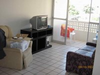
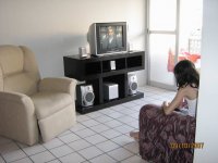
The place is delicious, 500 meters from the beach, wind is soft and temperature nice
A lot of ligth and soft wind blowing all day...during nigth the temperature goes down...but you can listen bats and falcons hunting during the nigth...very good.
regards,
Carlos
A lot of ligth and soft wind blowing all day...during nigth the temperature goes down...but you can listen bats and falcons hunting during the nigth...very good.
regards,
Carlos
Attachments
Hello my friends..
Hola a todos. Estoy esperando los resultados para empezar a construir el DX HD II. Aquí les dejo una imagen de mi SMPS +/-45v que construi para mi auto.
Saludos y respetos.
Fernando
Hola to all. I am waiting for the results to start constructing the DX HD II. Here I leave them an image of my SMPS +/-45v that build for my car. Regards and respects. Fernando
Attachments

Oh!... this interests me, please, send to my mail
the schematic and coil construction details.
panzertoo@yahoo.com
Esto és mui bueno hermano...jo quiero el diagrama.
Gracias,
Carlos
...................................................................................
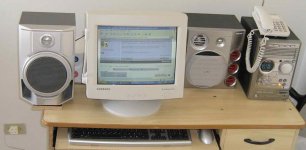
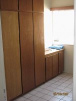
Image for friends,
My home is turning better as days goes passing by.
regards,
Carlos
the schematic and coil construction details.
panzertoo@yahoo.com
Esto és mui bueno hermano...jo quiero el diagrama.
Gracias,
Carlos
...................................................................................
Image for friends,
My home is turning better as days goes passing by.
regards,
Carlos
Attachments
Ok 1 step closer.......
removed dead transistors (it finaly ate the fake 5200 too) and some bd139s... reverted to vanilla DX bias servo...
Got out a roll of thick solder with lots of flux in and redid all solder points.
Powered up expecting no current draw or instant failure again... but hey... it was only pulling 1.6A....
Powered down, gave the pot a few turns, powered on again... and it came down a bit, I knew it was working so advanced it some more and eventualy got it biased to 500mA...
If only this was the end of it... but I have about 300mV of offset...
Achieved by turning trimpot by input diff pairs... I thought it was not supposed to do anything in this config...
Please advise further....
At least the knot in my brain let go now... and I can have some sleep tonight.... boy has this amp spoiled my Saturday.
Now I think I can probably fix a bunch of 70s and 80s amps with the skills learned.
Carlos, glad to see ou settled in and still healthy and happy with the environment...
Car subwoofer record goes to Brazil!
When you're trying to picture how loud this 180.5db subwoofer that set the world record for the loudest sound for a single sub is, you can't picture jet planes or chainsaws or firecrackers. No, you need to go a bit higher—into the realm of atomic bombs and nuclear disasters. So yes, this Digital Designs 9918Z 18-inch subwoofer that's powered from four Stetsom KD amps at 26,000 watts is a rolling nuclear explosion when it rolls down your street. That'll show the kids (and the old man with the heart condition) who's boss.
An externally hosted image should be here but it was not working when we last tested it.
Car subwoofer record goes to Brazil!
When you're trying to picture how loud this 180.5db subwoofer that set the world record for the loudest sound for a single sub is, you can't picture jet planes or chainsaws or firecrackers. No, you need to go a bit higher—into the realm of atomic bombs and nuclear disasters. So yes, this Digital Designs 9918Z 18-inch subwoofer that's powered from four Stetsom KD amps at 26,000 watts is a rolling nuclear explosion when it rolls down your street. That'll show the kids (and the old man with the heart condition) who's boss.
Those folks loves to show their sound at maximum volume.
Some of them you can feel the sub bass punch.... when they come distant you can perceive windows shaking.
It is too much, and awfull when they decide to park near your home and to open all doors.... a hell in our life.
Laws against that kind of abuse is starting to be created in my country...people use to be free to polute with sound...also they had the use, now reduced, to burn trash, garbage, in special when they have trees that fall leaves, than they put all things together and start a polution.
Law is old....burning inside you land, not one can touch you..problem is that smoke goes to whole world, not only into the burner home.
Well...i perceive advances, those last 10 years, we are much better than the early past...i hope we will reach the most developed communities, related education, in the next 30 years.
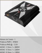
The Stetsom adress:
http://www.stetsom.com.br/br/Default.aspx
regards,
Carlos
Some of them you can feel the sub bass punch.... when they come distant you can perceive windows shaking.
It is too much, and awfull when they decide to park near your home and to open all doors.... a hell in our life.
Laws against that kind of abuse is starting to be created in my country...people use to be free to polute with sound...also they had the use, now reduced, to burn trash, garbage, in special when they have trees that fall leaves, than they put all things together and start a polution.
Law is old....burning inside you land, not one can touch you..problem is that smoke goes to whole world, not only into the burner home.
Well...i perceive advances, those last 10 years, we are much better than the early past...i hope we will reach the most developed communities, related education, in the next 30 years.
The Stetsom adress:
http://www.stetsom.com.br/br/Default.aspx
regards,
Carlos
Attachments
Destroyer X - SMPS
Dear destroyer x. To your orders. Here this the schematic one and PCB. Regards. The primary one of the transformer they are 5+5 turns with central tap and the secondary one 14+14 with central tap. The voltage regulates it with the Zener diodes.
Dear destroyer x. To your orders. Here this the schematic one and PCB. Regards. The primary one of the transformer they are 5+5 turns with central tap and the secondary one 14+14 with central tap. The voltage regulates it with the Zener diodes.
Attachments
- Status
- Not open for further replies.
- Home
- Amplifiers
- Solid State
- Destroyer x Amplifier...Dx amp...my amplifier