Hi Carlos,
The DX amplifier bass quality can be similarly improved by fitting larger rail 'C's, though without sacrificing power output by fitting series regulators.
This is why I suggested fitting larger value on board capacitors and wiring two more power 'smoothers' close beside and directly to the board. These isolate the input stages from rail current induced phase shifted voltage feedback.
Cheers ......... Graham.
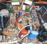
dx amp ...my amplifier
Carlos
Is it possible to make provision in the PCB design, for either an additional series zener diode in the capacitance multiplier,(perhaps vertically mounted to save space) or a wire link ? This would enable people with higher rail voltages to increase the front end supply a little higher than the nominal 33V.
Zener diode values above 33V are hard to obtain, so this might help.
Regards
SandyK
ostry & Klaas
Thank you for the information, greatly appreciated.
Carlos & sandyK,
Funny you should mention this, I was just reading ...
http://users.ece.gatech.edu/~mleach/lowtim/part2.html
recommending series zeners as a matter of course. I'll see what I can do when I get home.
Any other tips on eagle or layout suggestions are also welcome
Yes Graham.... a good option..people can remove the rail transistors if they want
The can include a wire jumper from the place where we had colector and emitter and include big condensers into the rail..also they can use resistance into the colector to emitter places.
This is up to them...a very good idea....but, take a read into the thread...i have already explained my position about that.
thank you,
regards,
Carlos
Good dear Ecat...if possible, let room to big condensers, as people may decide to use
Them, in the place of electronic regulator (i prefere this last one)
But Doctor Graham Maynard said will be good and will not loose power..so...if this option is possible, having room into the board without "kill" all your work...maybe interesting.
Of course, those condenser can be out from the board too..without any modifications..if you perceive problems to "create" room to 2200uf condensers, or even bigger (size)..than relax as people can install them out of the board.
The orange frame schematic, is the result of Graham Maynard's suggestion...it is up to you to use his idea.
I prefer the official schematic, the one using series regulators as i have told you... i have tested, compared, and despite the losses of power sounded better..clearly better..
The blue and green frame schematic published is the last update schematic, also schematics made by Ecat are being constantly revised...and he is publishing the last one...so...go backwards and you will see them.
Graham is a great designer...so...to follow his suggestion or not is up to you...also the differences are not so "astronomic" that way...it is up to you.
regards,
Carlos
Attachments
It is wonderfull to have more options of boards
This one you show Nordic, seems to me that has waste space into the left.
Watch the board cutted...it may be this size if you want.
Thank you...and go ahead..offer options to us..than people may be confortable having choices.... but be prepared to give them support about your board.
regards,
Carlos
This one you show Nordic, seems to me that has waste space into the left.
Watch the board cutted...it may be this size if you want.
Thank you...and go ahead..offer options to us..than people may be confortable having choices.... but be prepared to give them support about your board.
regards,
Carlos
Attachments
remember those caps still have to be made the same size as the big front ones... 22mm
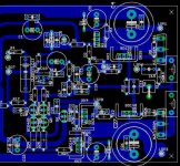
Main objectives were reducing sharp corners... acid collects there and eats through more during etching...also it is not the best way for the magnetic fields surrounding the traces to meet each other... and Tesla's wisdom of changeing the direction of forces as gradualy as possible to conserve energy.
Reduceing trace lenghts (inductances) between components.
Also I had to make up for my bad star ground last time, so I might have overcompensated in that category... it looks bigger than it is width 0.4" - I can see a few improvements still, didn't even notice I can get rid of Link1 yet...
Nordic,
I very much like the curves, nicely done")
Link1 was the first thing I noticed, lol, auto-route was having a fit without it !
Solving the layout is indeed an interesting puzzle. Going from a heap of components to a pile on the board thinking 'these will never fit'. Then suddenly a pattern emerges and before you know it you're thinking 'wow, all that space'.
Personally, I just like playing, sometimes fighting, with the auto-router.
One thing, I was trying to allow a lot of space around the output resistor, space for the coil. Carlos, can the resistor + coil be mounted off board ? If yes how far away from the board is realistic ?
I'm thinking I may try a board rotated 90 degrees a la klaas .
Carlos,
10 000uF 50v or 63v !! Not exactly small then ? <chuckle>
I very much like the curves, nicely done
Link1 was the first thing I noticed, lol, auto-route was having a fit without it !
Solving the layout is indeed an interesting puzzle. Going from a heap of components to a pile on the board thinking 'these will never fit'. Then suddenly a pattern emerges and before you know it you're thinking 'wow, all that space'.
Personally, I just like playing, sometimes fighting, with the auto-router.
One thing, I was trying to allow a lot of space around the output resistor, space for the coil. Carlos, can the resistor + coil be mounted off board ? If yes how far away from the board is realistic ?
I'm thinking I may try a board rotated 90 degrees a la klaas .
Carlos,
10 000uF 50v or 63v !! Not exactly small then ? <chuckle>
Here it is a little bit further along... Klaas did not sound 100% happy with his layout yet... so I will go with this standard "proven" Greg Erskine type layout, with seperate ground traces. I also visualised the inductor as an offboard job...and of course the output transistors lie flat... I am stil going to change the package of the output transistor to a symetrical one... what cat used is common, but if I am starting to understand some thermal distorion theory, you dont want dissimilar thermal potentials on the 2 connections to a resistor.... it will probably make .00000003% diffirence, but I'd fell 100% happy for following my beliefs....
P.S. on good advice I Tipexed the autorouter button out...
P.S. on good advice I Tipexed the autorouter button out...
Attachments
Re: Good dear Ecat...if possible, let room to big condensers, as people may decide to use
Interesting concept. I've seen discussion of separate supplies for the front end, but this approach is simpler. Of course, the trade off is a little loss in output power, but much less than the class A camp gives up. For DIY'ers, it may have another benefit. Sometimes builders are looking to make something with components they have in hand. If your power supply transformers are a bit high in voltage for your input transistors, this could be a way of staying within safe limits. I think you hinted earlier that the good sound may be due to more gradual clipping of the front end, as compared to the output end. That would be something that should show up well in simulation.
On another earlier post, you mentioned that you did not want to make the amp "too good", as it would be unfair to commercial vendors. Of course, I think it's fair and right that trade secrets learned in trust are not used or disclosed without permission. But I don't think that there is anything at all wrong with making the best amp you can, just using generally available methods learned through the course of a lifetime, and not learned in confidential communications. Of course, the line between these two pools of knowledge is not always perfectly clear, so that is up to how it feels to you.
In any case, I don't think you will affect commercial sales a lot, as I doubt that there is much overlap in the markets. Look at the experience you have had with your simplest version - lots of little problems with construction errors, faulty components, etc.. Diy'ers must be willing to put up with these things. Also, protection schemes are limited, and even safety issues are the responsibility of the builder. People who buy commercial units don't want, nor expect to deal with such issues. Even builders of highly developed kits expect perfection and are likely to blame the vendor for builder mistakes. For now, I won't buy any commercial amp or pre-amp, or speaker, but not because of quality or cost. The only reason is that I want to make them myself. The group of people who DIY mainly for cost/quality issues is small and very likely an unprofitable target anyway for a high quality vendor of unique fully developed amplifiers - note, for instance, that Hugh's latest and greatest are not available as packages of bits waiting for assembly.
Cheers,
Sheldon
destroyer X said:prefer the official schematic, the one using series regulators as i have told you... i have tested, compared, and despite the losses of power sounded better..clearly better..
Interesting concept. I've seen discussion of separate supplies for the front end, but this approach is simpler. Of course, the trade off is a little loss in output power, but much less than the class A camp gives up. For DIY'ers, it may have another benefit. Sometimes builders are looking to make something with components they have in hand. If your power supply transformers are a bit high in voltage for your input transistors, this could be a way of staying within safe limits. I think you hinted earlier that the good sound may be due to more gradual clipping of the front end, as compared to the output end. That would be something that should show up well in simulation.
On another earlier post, you mentioned that you did not want to make the amp "too good", as it would be unfair to commercial vendors. Of course, I think it's fair and right that trade secrets learned in trust are not used or disclosed without permission. But I don't think that there is anything at all wrong with making the best amp you can, just using generally available methods learned through the course of a lifetime, and not learned in confidential communications. Of course, the line between these two pools of knowledge is not always perfectly clear, so that is up to how it feels to you.
In any case, I don't think you will affect commercial sales a lot, as I doubt that there is much overlap in the markets. Look at the experience you have had with your simplest version - lots of little problems with construction errors, faulty components, etc.. Diy'ers must be willing to put up with these things. Also, protection schemes are limited, and even safety issues are the responsibility of the builder. People who buy commercial units don't want, nor expect to deal with such issues. Even builders of highly developed kits expect perfection and are likely to blame the vendor for builder mistakes. For now, I won't buy any commercial amp or pre-amp, or speaker, but not because of quality or cost. The only reason is that I want to make them myself. The group of people who DIY mainly for cost/quality issues is small and very likely an unprofitable target anyway for a high quality vendor of unique fully developed amplifiers - note, for instance, that Hugh's latest and greatest are not available as packages of bits waiting for assembly.
Cheers,
Sheldon
Yes Sheldon...but the biggest discoveries are made secret..and those things
really "sounds"...it is difficult to produce a top performer if you had not discovered the subcircuit that produces the special quality.
You just cannot use it..because it is the most important difference that decides the amplifier sonics.
We can go near...but we never match...... the possibility to match is to use that circuit..and you cannot because not yours.
If some circuit can be so good that way... in such a good way that will almost decide the winner into a comparison..for sure will not be interesting to see people using it...because the quality advantage of the commercial product will disappear...well...you know those things.
If i succeed, someday, to make something even better than my dear friend Hugh Dean...i will not publish.
Not fair to publish something for free, that will bring to me only some thanks and create problems to my friend's sales..even the loss of one single customer is to much to me...i will not be responsable.... the guy is my friend, and my teacher..my decision..beeing better than his products...not to publish.
I also think that if we can reach the peak of high end...not very interesting to post.... as we will killing hundred of factories...why people will buy those top end amplifiers if they have a diy schematic so good or better?
Of course, market is bigger...not only diy exists in this world...and in special, diy do not buy those expensive retail things..so... probably will not bother Hugh...but try to imagine someone that wants exclusive, customized special high end circuits...and pay without complain..not bothering about how much cost..if this one discover, one day, that all diy audio community has those secrets of quality for free!... the customer... of course, will feel himself as an idiot...everybody can have it, for free, and he paid thousands dollares.
regards,
Carlos
Dear Ecat...if big...try to produce board that can hold 1000 uf or 2200uf
This may be reasonable..if the guy decide to construct Graham idea to rail filtering...he can use condensers out of the board.
If will kill the board beauty..go to the original, official, green and blue schematic.
Man!..you are cooperating, helping me...the board is yours,even beeing mine the schematic..you can do whatever you want..to include or exclude...be free.
I am happy you have made exactly as the schematic...if problems to let some room to modifications....just do not let room to modifications and let's be happy.
Inductor will not create too much problems if distance form the board copper lines was bigger than 4 milimeters...also, if we have the chance to make our choices were to solder the output side..will be good (the sketch)..will be better...but we can arrange ourselves without that sophistication too.
regards,
Carlos
Attachments
Copper lines are always inductors.
I had one oscilator used to tune Aircraft transmissions to the Airport.... around 125 Megahertz, FM.
I have made a coil with one single turn...was not good with that variable capacitor i had....than i have tried to open that one single turn coil into a half coil...frequency increased..but not enougth..than i use that wire, the one used as a coil, stretched as an straigth line.... than i could tune.
So... a single piece of wire..even the one seems that are straigth...maybe not so straigh...as straigth lines over the planet earth will not be straigth..the planet is curved...so... even small fraction of degree you may have.
Because of that, curves are a hell...also 90 degrées angles are problematic..better to make the copper lines as much short as possible..following the rule that the "smallest distance between two points in the space is the straigth line"...but on planet earth..and maybe in surrounded space..the gravity forces and the earth curves will not make your line be really straigth..well... a scientist told me that once...and this make sense to me.
Old cel phone had coils made into the copper lines, board that had printed coils.
When you have an inductance, and a capacitance in parallel..you will have a tuned circuit.... join to that an HF high frequency transistor...ahahahahha... oscilation will result!
regards,
Carlos
Copper lines are always inductors.
I had one oscilator used to tune Aircraft transmissions to the Airport.... around 125 Megahertz, FM.
I have made a coil with one single turn...was not good with that variable capacitor i had....than i have tried to open that one single turn coil into a half coil...frequency increased..but not enougth..than i use that wire, the one used as a coil, stretched as an straigth line.... than i could tune.
So... a single piece of wire..even the one seems that are straigth...maybe not so straigh...as straigth lines over the planet earth will not be straigth..the planet is curved...so... even small fraction of degree you may have.
Because of that, curves are a hell...also 90 degrées angles are problematic..better to make the copper lines as much short as possible..following the rule that the "smallest distance between two points in the space is the straigth line"...but on planet earth..and maybe in surrounded space..the gravity forces and the earth curves will not make your line be really straigth..well... a scientist told me that once...and this make sense to me.
Old cel phone had coils made into the copper lines, board that had printed coils.
When you have an inductance, and a capacitance in parallel..you will have a tuned circuit.... join to that an HF high frequency transistor..... oscilation will result!
regards,
Carlos

- Status
- Not open for further replies.
- Home
- Amplifiers
- Solid State
- Destroyer x Amplifier...Dx amp...my amplifier