Re Dx Turbo Version
Hi Carlos")
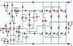
Updated the scematic with new C18 value and connection. Check schematic below. After reading your last post I will keep C10/C11 as is. R10 and R12 changed to 1Watt resistors.Is this ok? Will start with the PCB layout tonight.
Thanks
macd
Hi Carlos
Updated the scematic with new C18 value and connection. Check schematic below. After reading your last post I will keep C10/C11 as is. R10 and R12 changed to 1Watt resistors.Is this ok? Will start with the PCB layout tonight.
Thanks
macd
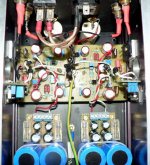
Attachments
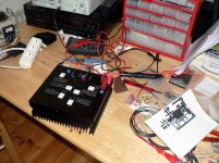
I don't think its the pot........its a brand new expensive one from RS and the meter moves very smoothly with it, maybe something on the new veroboard VBE boards..
Ouch, just rubbed flux into my eye....
Man it is sooooooooooo close.... just got to get this channel working again and I can scew the top and bottom on...
Ouch, just rubbed flux into my eye....
Man it is sooooooooooo close.... just got to get this channel working again and I can scew the top and bottom on...
Hi Nordic,
The output devices will not conduct until they are biased.
At the point where they become biased, the input stage plus zener, the bootstrap resistors and drivers must all conduct before the output devices do, so the change in total rail current will not increase linearly when adjusted through the bias point due to the output transistors suddenly providing additional gain.
Did you try shorting the input when you set the bias ?
Cheers ........... Graham.
In case open input was allowing some unwanted effect as the bias was being adjusted such that the output stage conduction pulls the output potential one way or the other.
When not there, it is not easy making suggestions, especially when I cannot be sure that anything is actually wrong with the amplifier itself.
Cheers ....... Graham.
When not there, it is not easy making suggestions, especially when I cannot be sure that anything is actually wrong with the amplifier itself.
Cheers ....... Graham.
No problems Macd.... fine!..... well, my dear Nordic
If you continue to search for legs in snakes you may convince yourself that they have legs!
When you power on, because of zener and biasing resistances, the first stage and Vas goes immediatelly working, into conduction...they have that consumption..something around 20 or 25 miliamperes....but...depending the bias trimpot settings, the drivers and output can be switched off (not conducting...so, no consumption)...but you will go advancing your trimpot and the base to emitter voltage, into drivers and output transistors goes increasing...and them 400 milivolts and they do not conduct, so, do not produces consumption of energy..... than you go further and they switch on and start to conduct, they start do drain current...this point you have is when you perceive the current increase.
There's nothing wrong with the amplifier.... dear Nephew, the problem is you that are searching for defects...if you insist, you will find a lot of defects.
For instance...into the differential, measuring the VBEs...you will see that the first one will measure 590 milivolts (example Nordic..do not go to find the same measurement in your board..will not find the same...this is just a reference for explanations)...and the other will measure 593 milivolts...and will be floating to 591, ... 592.... 593..... 594.... 595..and them go to 590...this will happens, and the input transistor compared with the feedback one (Q2) will have the off set voltage as difference...installing two multimeters, one will measure those 3 milivolts of off set more than the other (if 3 milivolts...no problem...can be 4,5,6,7,8 9,10, 11...also can be -2, -3, -4, -5... do not worry...be happy.
Also do not search for 590 milivolts in all transistors..this never happens...one will be 600, other 560....other one will be 605...and other will be 572...so...relax...if you really want perfection...only having some dosis of poisson and going to heaven..... but even there, dear Nephew, you will find problems, defects...people told me that anjos do not have sex...can you imagine that!...sweet anjos, beautifull girl.... and no sex?
Also you condensers, the ones market 47uf, they do not have this...try to measure and you will find more than 50...maybe 60uF.
resistances, when measured, show different values...your multimeter, measuring twice, may show different values over the same resistance...also you supply...depending the mains.. your voltage can go 1 or 2 volts up and down.
ahahahha...life is not perfect.... the hell for those perfectionists..they will be very unhappy...in my point of view...ahahahah... they deserve!
A very small touch into the trimpot, even your multiturns, will make the current give a jump...increasing...this is normal.... seem the output started to conduct.
The main difference between practice and theories, is that skilled guys knows that.... theorical folks start to shake, very shocked with those differences....
- How deer that?.... i have not calculated this way?
hehe
regards,
Carlos
this is not normal.A very small touch into the trimpot, even your multiturns, will make the current give a jump...increasing...this is normal.... seem the output started to conduct.
Hi Carlos, not looking for defects.... remeber I have no experience to compare this with... all brand new.
Because I set the first channel to 50mA without any problems like these, I thought I'd try for the same with the other channel... whell what do I know... It does not seem to want to be biased this low...
To make things worse I walked off somewhere with the only screwdriver that fits in those tight spots, somwhere between this morning and now....
I'm realy excited, I think the fix is just around the corner.
Fine Macd, the schematic is OK!
This resistance, R18, may need adjustment of value.
After construction, you must read the output drivers and output power units VBE...they must be not so different... increasing this resistance you may equalize that.
Adjusting your VBE to 2.4 volts, measuring from colector to emitter into the VBE multiplier transistor, you may expect the distribution of those 2.4 volts into 4 portions of 600 milivolts ( 4 X 0.6 = 2.4 Volts )
But this do not happens always...sometimes you will have 630 into the drivers and 570 into the output unit.... than you will need to adjust this resistance to share this voltage in a better and fair ratio.
This depends your transistors...the gain and the models you will choice..so.... have to construct, to measure, and them to adjust this to fine tuning.
Also the bias may need some "fine tuning".... install a headphone into the output and adjust your signal source to have a very low volume..observe voices.... perceive that underbiased they appear failing....harshy....distorting...than you go increasing till this effect (defect) finishes.... this is the optimum bias....the lowest possible current that will force all transistors into conduction.
regards,
Carlos
Attachments
"A very small touch into the trimpot, even your multiturns, will make the current give a jump...increasing...this is normal.... seem the output started to conduct."
This pretty much describes it.. except its is not over the whole range of the pot... only within a very limited region... somewhere below 55mA it looses its beans........
The other channel was so easy to bias... so its all down to diffirences between the components then?
P.S. Carlos, check previous page, we posted at the same time...
AndrewT said:this is not normal.
This pretty much describes it.. except its is not over the whole range of the pot... only within a very limited region... somewhere below 55mA it looses its beans........
The other channel was so easy to bias... so its all down to diffirences between the components then?
P.S. Carlos, check previous page, we posted at the same time...
It does seem to involve both trimpots... I reset the offset trim, then did the bias again for 60ma... but multimeter kept increasing at about 1mv/sec... offset was way off, so I brought it down a bit... at some point I can get reasonbly stable bias but then we are looking at about 115mv offset...
Best case I can get about 50mvdc offset..........with slowly increasing bias........ sigh.
Trying to go lower makes the output stage switch off again...
Best case I can get about 50mvdc offset..........with slowly increasing bias........ sigh.
Trying to go lower makes the output stage switch off again...

- Status
- Not open for further replies.
- Home
- Amplifiers
- Solid State
- Destroyer x Amplifier...Dx amp...my amplifier