Re: Re: Re: Destroyer X
Hello
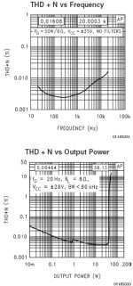
As you can see those graph for a LM3886 chip amp, the distortion are raising at high frequency and at low level output, remeber that in a transient situation on a real speakers it will be worse.
Gaetan
juergenk said:
can you give an example?
this is a typical arguement in the valve vs. silicon debate.
However, everytime I look onto published THD charts, the THD vanished into noise at low levels.
regards
Hello
As you can see those graph for a LM3886 chip amp, the distortion are raising at high frequency and at low level output, remeber that in a transient situation on a real speakers it will be worse.
Gaetan
Attachments
To my friend Riche sine instructions.
R6 - please use 3K9
Vr1 - first adjustment set it to 2800 ohms
Vr3 - start with 736 ohms
Prefer to introduce attenuator in the input (i will provide image) to avoid tweak the gain network...keep R10 into the standard value ...having too much signal level into the output...then, install resistive attenuator.
Introduce the 100N.... image will be provided.
Each output transistor (minimum of 2 pairs) will need it's own base resistance and emitter resistance.
Adjust current from 60 to 100 miliamperes.
Adjust your off set to lower than 4 milivolts.
And be happy!
" Dx amplifier is not a ghost....it exists and playing in many places around the world....also near me "
regards
Carlos
Attachments
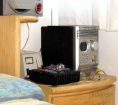
Please, observe the image was made now!
It is playing...and very nice.
Signal must be adjusted in level to the amplifier input.... made to work fine with 750 milivolts....adjustments will be needed to use higher levels...and above some certain level it will distort anyway.
regards,
Carlos
It is playing...and very nice.
Signal must be adjusted in level to the amplifier input.... made to work fine with 750 milivolts....adjustments will be needed to use higher levels...and above some certain level it will distort anyway.
regards,
Carlos
Attachments
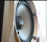
The amplifier is very strong into the bass area
You can watch a single cicle moving slowly the speaker diafragm.
So.... if you have noises, subsonic tones...better to reduce your input condenser till 82N
See the image.... 10 Hertz!.... pumping 80 watts RMS.
The unit is a bomber...or a bombardier.
regards,
Carlos
You can watch a single cicle moving slowly the speaker diafragm.
So.... if you have noises, subsonic tones...better to reduce your input condenser till 82N
See the image.... 10 Hertz!.... pumping 80 watts RMS.
The unit is a bomber...or a bombardier.
regards,
Carlos
Attachments
This is the input attenuator...add those two resistances....yeah
keep the circuit as published in Greg forum.... those resistances are soldered under the board...and insulated with plastic tube.
This will make the amplifier hold 2 Volts of audio.... 2 Volts RMS of audio without distort.
regards,
Carlos
keep the circuit as published in Greg forum.... those resistances are soldered under the board...and insulated with plastic tube.
This will make the amplifier hold 2 Volts of audio.... 2 Volts RMS of audio without distort.
regards,
Carlos
Attachments
R6 will feed the differential and the zener.
zener current is almost ten times the long tail current.
But with your voltage increase, the zener will work too much hot and can burn...this way, replace the 2K2 original resistor by a 3K9 one.
regards,
Carlos
zener current is almost ten times the long tail current.
But with your voltage increase, the zener will work too much hot and can burn...this way, replace the 2K2 original resistor by a 3K9 one.
regards,
Carlos
Attachments


You will have, dear Riche, one of the new pair of constructors..together handsome
guy.
The current that will be crossing the Dx amplifier will be very big.
this will produce variations in the supply voltage...better to decouple the off set trimpot using a capacitor.
Customized for high power versions.
Please, install this new capacitor to high powered versions only.
regards,
Carlos
Attachments
The bias adjustment to provide you around 70 miliamperes of current
during the stand by mode...during your set up..without audio in the input.
Start with something around 700 ohms.
Never start any amplifier before install protective resistances in series with the supply...observe Greg home page, Dx amplifier instructions.
Read entirelly, not only the thread, but also the home page..will be more safe this way.
Working with those voltage may be dangerous to you...plus 60 volts and minus 60 volts (a little bit more) will be terrible!...be carefull...
take care!
regards,
Carlos
Attachments
You output will need, at least, two output pairs.
If you ask me what i would prefer... i will tell you 4 output pairs, because this will help you when using crazy speakers....as during 2 ohms frequencies you will be able to produce more than 500 watts RMS over 2 ohms..... depending of the supply capacity of current.
Use one resistance to each output transistor base.
Use one resistance to each output transistor emitter.
If you decide to use long cables to output...normal, cheap, parallel wires...better to install an output coil in parallel with a 10 ohms resistance..... 1 watt resistance wounded by 22 turns of 1/2 milimeter diameter wire as minimum.
If you perceive something missed into the simulation i have made, special for you Riche, obbey what is in the official home page schematic....the 220 picofarads resistance is used into the input transistor as shown in the schematic.
regards,
Carlos
Attachments

Ahhahha..... Nah!... a little less awfull than that dear Nordic
Highly appreciated your good mood dear Nordic.
Riche intentions to construct and Microp courage and decision made me happy.
The Rumanians disappeared.... they left me alone.... but i am lucky...they gone and 2 new more arrived.
They may return...i hope with good news.
regards,
Carlos
Highly appreciated your good mood dear Nordic.
Riche intentions to construct and Microp courage and decision made me happy.
The Rumanians disappeared.... they left me alone.... but i am lucky...they gone and 2 new more arrived.
They may return...i hope with good news.
regards,
Carlos
Attachments

Please Riche, read the post suggested by Microp
You will need to replace the drivers and voltage amplifier transistors to units that can hold bigger voltage.
That post suggest better transistors to hold the voltage.
R6, R12 and R13 will dissipate more power.... 0.5 watt to 1 Watt will be need to those positions.
You may have he need to increase C14 to 47 picofarads or
more..because of voltage increase.
The better will be to use 4 transistor pairs, because the dissipation will be high..to divide the heat into 8 transistors....of course you can accept some risk using two pairs...but it is a little dangerous..if a continuous tone enter the amplifier...a square wave for instance..having high level...or even an oscilation can kill the output units.
Sometimes, economy can be very expensive...as we go using not enougth parts and this results in some output transistors burned because some accident.
You are the fourteenth guy that have asked special schematic, adaptations to use bigger supply voltage....no one of those asked special schematics have constructed, they have just produce more work to me, i hope you will be the exception.
http://www.diyaudio.com/forums/showthread.php?postid=1136293#post1136293
regards,
Carlos
I have to say i am extremelly happy as i could reach so distant place as Látvia..
called Letônia in my language..... Riga is the Capital, the main town.
I had a wonderfull friend, he is in the heaven now a days.
His name was Yanis Ivars Rittins, and he came from Letônia (látvia)
Very good to have those folks around...wonderfull people!
regards,
Carlos
called Letônia in my language..... Riga is the Capital, the main town.
I had a wonderfull friend, he is in the heaven now a days.
His name was Yanis Ivars Rittins, and he came from Letônia (látvia)
Very good to have those folks around...wonderfull people!
regards,
Carlos
Attachments

Re: Ahhahha..... Nah!... a little less awfull than that dear Nordic
They didn't left. They are just very bussy listening to the DX amp") Switching speakers arround, throwing all kinds of music and sounds to it.
Switching speakers arround, throwing all kinds of music and sounds to it.
The results are good until now. Maybe a bit to much low range, how to put it, not very well controled. You have mentioned some pages befor something could be done to have better quality low range (not more but better controled).
Voices and treble are SUPERB.
Thank you Carlos, thanks to al DX team.
I'll build my own DX soon and UsernameX allready decided he will build another one
destroyer X said:...
The Rumanians disappeared.... they left me alone.... but i am lucky...they gone and 2 new more arrived.
They may return...i hope with good news.
regards,
Carlos
They didn't left. They are just very bussy listening to the DX amp
Switching speakers arround, throwing all kinds of music and sounds to it.The results are good until now. Maybe a bit to much low range, how to put it, not very well controled. You have mentioned some pages befor something could be done to have better quality low range (not more but better controled).
Voices and treble are SUPERB.
Thank you Carlos, thanks to al DX team.
I'll build my own DX soon and UsernameX allready decided he will build another one
Time to emerge from the shadows
I read through this thread last week and a most interesting read it is too, even if it does keep you awake until six a.m. and make you late for work.
Carlos, first may I thank you for sharing your creation, thoughts and humor. Second, my thanks also for standing firmly by your conviction that exotic parts, while an option, may add little to the final result. As I'm a diy amp virgin this has done wonders to quash the paranoia that results from the fear of choosing the 'wrong' parts. This 'wrong part paranoia' has also been greatly eased by your decision not to include alternatives and your insistence on the one PCB layout.
All of the above persuaded me that my first diy amp, the amp I would build, would be this one.
At the moment I'm using six channels of a Yamaha AV amp in my poor mans tri-amp setup. This is the amp I'm replacing, so six baby DX's are on their way. Parts are here (many the wrong size, lol), PCB's are made, drilling has begun and now I'm procrastinating
Symasym would be a better choice ? But no. DX works, ximple, neither xpensive nor xotic, just build it !
Being my first post I'm not sure if the attached image will show, but if it does please be gentile with me, this is only the second time I've tried making PCB's.
Sound Stage: This fascinates me too. As I use a digital cross-over I've spent some time playing with driver delays and phase, some of the results are astonishing. I remember sitting down and pressing the play button at which point Debbi Harry appeared no more than 3 feet in front of me. Wow, an amazing effect that ultimately I had to abandon. Having vocalists so close left me feeling that my personal space was being invaded :O
I felt a little bit more controled, the bass, reducing it since the input.
Try to install a 82N capacitor into the input.. substituting others that you have there... a single one to block subsonic and attenuate low end
Try to reduce R11 to 33K
Reduce C10 to 100uf
Install 0.47 ohms emitter resistances under the board.... this is the worst modifications i think, because turn the bass more controlable, less loosen but also much less punchy...the thunderstorm punch of the bass is lost in the name of superb fidelity, astonishing quality and impressive capacity to hold instruments producing nice figure at numbers...... i do not like the result, but if you think into absolute high fidelity, this modification may help to produce the result you want.
Yes...i have made it...have tried it...and i am still listening that option.
It is terrible, and also wonderfull, to see how good was Aspen amplifiers into the decisions he made in his amplifiers...... Aspen people do not accept other resistance than 0.47 ohms in that position.... listening i have perceived why..... a correct decision to highest possible fidelity...but loose the impact...loose the bass punch... the looseness, the imprecision into the control that produces some reduced damping.... a long decay.... a more long bass tone...the reverberation of a metal barrel hitted with wood protected with rubber and cloth in its hitting point.
The boooooooom.... turns boom! after those modifications...all them together produce those effects.
I am constantly tweaking..... i use to wake up at nigth to try something.... in my mind it is a need to try everything to see if it is possible to peak it a little bit more without enter Hugh sub circuits.
I am happy you have not abandoned Dx.... also very happy that you had perceived the qualities the unit really has...beeing very simple, ximple and cheap..... Bulgaria also offered to us, some bulgarian friends, one unit that may sound great too..... the exception is the output that may disturb a little when driven hard.
I am satisfied with your comments...good enougth,
thank you Usernamex and Charlie_fd
My 10 years old daugther, beloved Larissa, also thank you as she had helped me a lot during the design, calculations, production and testing... she is excellent in Mathematics and correct all my calculations.
regards,
Carlos
Attachments

Thank you Ecat by your preference....yes, i know you are into the decision process
No problems...relax and decide being calm and free.
Do not mind with pretty things.... that "big magic" that pretty amplifier sound pretty, or pretty good, is not real.
We have..... all of us.... some beliefs....they are simple and consequence of other life things we have learned.
That "wrong part paranóia" is terrible!.... there are many intelligent folks deeply submerged into that belief...... what this results?.... the one will never have sure of nothing.
The question is.... always:
"Using another combination of caps brands and caps materials can I have better sonics?"
They believe with the answer YES to this question.... more terrible..they are SURE!
This is hard... seems to me sometimes, alike a self punishment disturb of normality (standard behavior, statistically measurable inside a specific population under testings) ... people that need to suffer and prefer not to be sure of nothing...because sometimes, when you have sure you need to move, to take hard decisions, to block the continuity of sick things in our life...better to let them there.... as another combination of factors (parts, components) may be even worst!
The probe of the disease is that we can check those capacitors differences in a matter of seconds....just solder two wires and go replacing A to B.... ready to check if Polipropilene sounds better or worst than Paper, alluminium coiled with electrolitic oil.
I have tried with one friend.... while he was knowing the Silver Mica...he told me that Silver Mica sounded better... than i repeat the test several times...was blind testing that second time.... result did not reinforced Mica superiority...had not consistence...so...the belief change their decision...they perceive as better...fooling themselves.
Was hard to make it accept to be tested about that... i had to pay him with a 800 watts transformer!
No!.... a lot of folks do not do that....because will make the board dirty, will be ugly, during the experimentation we can have an accident....or even worst.....
- "have to wait to burn it"
This is the worst thing on earth!..... this way...nothing is measurable and evaluable using ears..have to wait..... and now you ask...
- "how long?"
The guy will tell you that is variable...maybe 5 hours...maybe 50 hours...maybe 150 hours...maybe one week...well.... this is the creation of unmeasurable terrible mistery!
Also, one burned in capacitor cannot be removed from amplifier A to amplifier B..... as impedance, or circuit characteristics do not matches..ahahahah.... it is interesting...and this comes from very intelligent people...now i know how exists people betrayed for years and never realised that...they do not want to know!...this is the reality...they want to fool themselves.
Ask those folks to make A to B!
They will answer:
- I have not the wires with the length neeeded...high quality, special wires, have not the needed length.
- I do not want to move all my stuff to prepare the scenery.
- I have not that switch.
- I have not someone experience to operate with switches and cables.... and i cannot know what was made there with cables...a blind testing ask that.
- It is almost impossible, having different amplifiers, different dinamic to adjust the same volume.
- The speaker used, can be more kind to one speaker than the other.
- I cannot replace the speaker under testing, as i have not other one.
- My room have not the correct acoustics... result may be wrong.
Well... they jump out... alike popcorn being cooked into an open can.
What can i do related that.... accept them, as i am crazy too.
regards,
Carlos
- Status
- Not open for further replies.
- Home
- Amplifiers
- Solid State
- Destroyer x Amplifier...Dx amp...my amplifier