Do you think that Jordan is the only driver which can do that?
what makes You think so?
it is just a historic example of good near/on-wall design, the "JX53" in "JX53 array" is there only to allow easier identification of specific design
JX53 seems to be pure midrange, and being more specific, upper midrange. Recommended XO around 200-500 Hz so you really have to design bass units which carry at least 3, maybe 4 octaves. Array of four fullranges bring more problems like phase cancellation.
Not only that, they're possibly the most fragile drivers in the world. I've never blown a driver that wasn't a JX53 or Jordan Module...and I've blown a few of those. Do not ask an array of four of them to do anything more than low-volume easy listening.
Frankly, there's nothing the JX53 can do that the Aura Whisper can't do better. The Whisper does have half the cone area (which also means better HF dispersion), but it has much more throw, and its motor (Aura's underhung NRT) is much better. For an array of 4, if one was into that sort of thing (I'm not), the Whisper is straight up superior, and costs less than a fifth as much.
My guess is that for small distances you must include a fraction of baffle width, as the front wave has to travel around it as well before it gets to the boundary.the reflected speaker image is exactly 1/2 wave behind the source at the frequency of the null
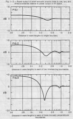
Allison was calculating the power response of a woofer against a boundary so he was integrating around a sphere. That is why he shows a dip at 0.3 wavelengths off the surface rather than the usual 0.25. 1/4 wave at 500 Hz is about 168mm.
Allison's article was "Influence of Listening Rooms on Loudspeaker Systems" from the late 70s or early 80s.
In a nutshell, the location of the drivers in relation to the boundaries, selection of crossover points were important to overcome the suckout. In addition it highlighted the need to keep all boundary dimension very different and not a direct multiple of each other as was shown in Fig1-3 where all dimensions are the same.
I've added these parts of the article for reference as it is useful in design and placement.
Attachments
I've added these parts of the article for reference as it is useful in design and placement.
Thanks for the clips they are indeed relevant.
Let me explain a little bit about my comment on the 0.3 wavelength and clarify Allisons three curves.
The key phrase is that he refers to "power output". Power is different than pressure or SPL, in that it seldom means at a point in space but is usually an integrated quantity around a system. The three curves of Allison are calculated by considering the response in all directions for a driver a given distance off of a surface.
Now if you come straight out from a surface the reflected image behind the surface is the maximum distance from behind the real speaker that it can be. It will be twice the distance the actual speaker is from the reflecting surface. If the real speaker is 1/4 wavelength above the boundary then the image is another 1/4 wave back, the units are 1/2 wave apart and complete cancelation will occur (and yes, bbggg is correct that you would have to factor in a little distance for bending around the baffle width itself).
Now if, rather than perpendicular to the wall, we go off at an angle from the wall we will see the distance between the source and its image diminish. We will go off on a diagonal and the diagonal distance between source and image will be diminished by the cosine of the angle. For the 30 degrees I mentioned it will be .866 of the true distanace to the boundary (times 2). As we increase the angle, and at the limit, we will be moving down the surface of the wall and the distance from the listener to source and listener to image will be exactly the same. The cancelation null will have moved up to infinite frequency, i.e.a little out of band. (Ground plane measurements, anyone?)
The reason this matters is that Allison is calculating power response, so he has to integrate all of these curves for his one power curve. He would be integrating the straight out curve with a null at .25 wavelength all the way to the plane-to-the-wall curve with no null at all.
In fact he shows three integrations with 3 different sets of limits. The single boundary case has the most washed out features and just a vestigal dip considerably above the .25 wavelength frequency. That is because he has to include the wide range of curves from 0 to 90 degrees in all directions and as he adds the curves near the single boundary the cancelation nulls are so much higher they wash out the original .25 wave null.
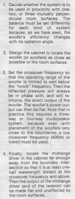
In the case of 2 boundaries he has to now consider the source and 3 images (the side wall image speaker, the back wall and the between-the-two reflected image speakers) and he is more constrained in how he can move around them for his integration, since he eventually runs into the side wall or back wall. For two boundaries you see more LF level since at lowest frequencies you have the in-phase summing of 4 elements, one real and three reflected. Additionally, the null is stronger and a little lower in frequency because of the angular constraint.
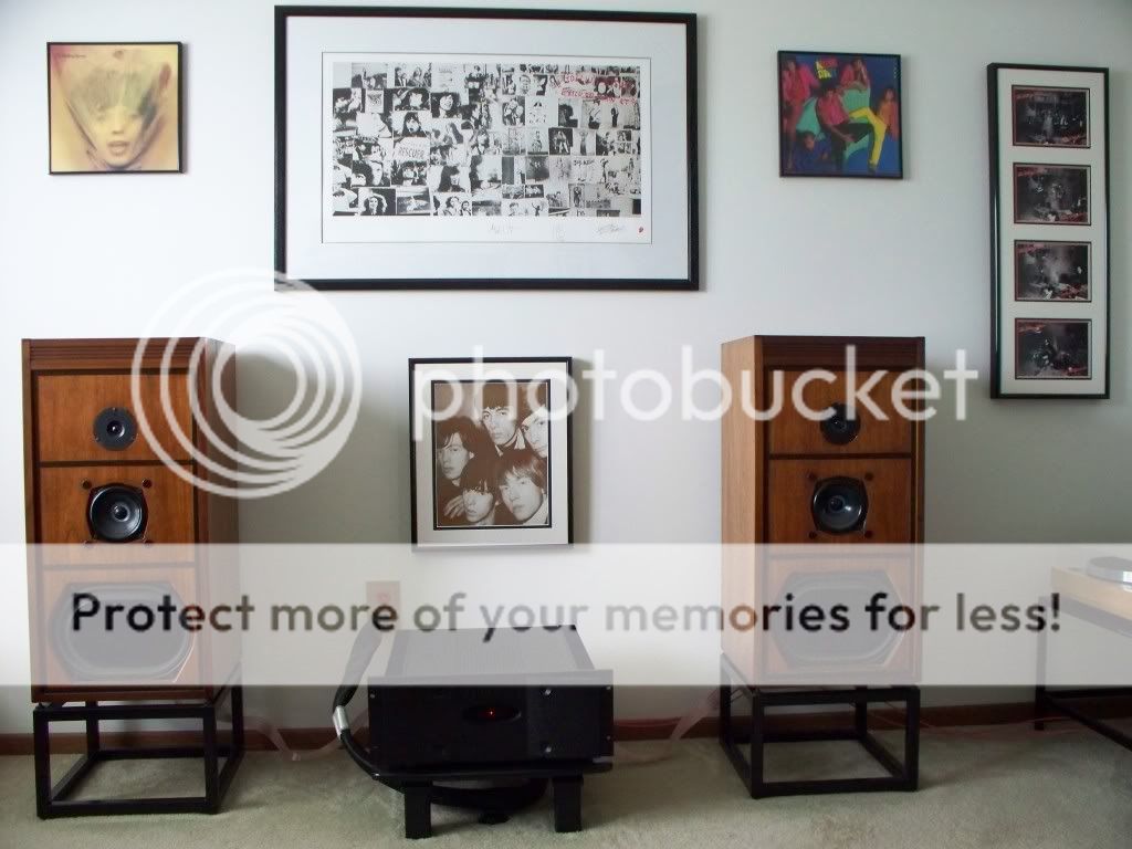
The final case is of a woofer in a trihedral corner, i.e. near 3 walls (okay, 2 walls and a floor). There are now 8 sources to consider and only 1/8th space to move around to solve the integration so again we see an increase in ultimate bass level and more dramatic wiggles in the curve with the null getting much closer to the .25 wavelength frequency.
The philosphical question is: which pertains to us or do we care about the power response at all? Considering the power response is a bit like asking "if I have an audience full of people, what is the average effect on all of them?" In truth we will sit at a particular position and will only care about the frequency response at that particular spot, so the SPL based on the diagonal distance is the relevant curve. Based on that the null at the frequency where the source is 1/4 wave off the surface, divided by cosine of the observation angle, is what we need to deal with.
I'm sure Jordan would agree.
David S.
The philosphical question is: which pertains to us or do we care about the power response at all? Considering the power response is a bit like asking "if I have an audience full of people, what is the average effect on all of them?" In truth we will sit at a particular position and will only care about the frequency response at that particular spot, so the SPL based on the diagonal distance is the relevant curve.
Power response is average of frequency responses of different degree angles (anechoic). How can we underestimate it because we ARE HEARING it in room where all radiation sums someway in the end?
In this case Allison is calculating a power response that is definitely non anechoic but rather a power response difference curve based on 1, 2 or 3 near boundaries.
But why would I be interested in a generic view such as power response when I can have the specific view of frequency response that can be exact for a real listening location?
We are hearing the frequency response at a location. The obvious proof is that bass changes as we move around the room. As we move near or away from boundaries or from peak to trough in standing waves the bass character constantly changes. How does power response help us in that regard other than in influencing the average of all posible positions?
David S.
I found some curves for the VS300 with wall bounce correction.
The first curve shows the response of the system in free space and against the wall. Blue is free space and green is on-wall. Lots of LF lift from the boundary but at 500Hz the reflected source is 1/2 wave behind and heavy cancelation occurs. The curve is fairly wide as well as deep and was clearly audible as sucking the midrange out of voices. Note that there should be higher harmonics of cancelation but they are fairly minimal since the system directivity is rising.
The second curve shows a few different EQ curves. At the top is a gray difference curve between the 4 pi and 2 pi responses. The EQ needs to be the inverse of this curve to fix the on-wall response. The fix I used was via the 2 1/2 way woofer networks. Green shows the upper woofer response that never changes. Red and Purple are the "lower" woofer responses, achieved by network switching. Red is the normal free space or 4 pi response. Boundary correction comes from the Purple curve.
The final set of curve shows the on wall response without correction (green curve) and the boundary corrected curve in red. I didn't fully drop the bass response to flat (nobody complains about too much bass.)
So there, it can be done. But remember that it only makes sense if you can guarantee that the boundary location is fairly consistent, as it would be with a wall bracket mounted system.
David S.
Dave: Thanks for the detailed explanation. Seems like a clever trick. However I did not understand one thing.
It looks like you are boosting the level at the dip with the lower woofer. If both upper and lower woofer are at the same plane, then the lower woofer will have the same reflection and hence suffer the same cancellation. It seems equivalent to just using one woofer and boosting the dip passband. This however would not work because it will also boost the reflection. They will continue to cancel each other.
Good question.
I haven't seen anything on the market beyond what was talked about and my own designs. Flush in-wall speakers don't have a problem as they are on the baffle. Bookshelf speakers have near-wall bounce problems but designers don't usually tacle the issue beacause the distance to the wall is variable. The null frequency would very with this distance.
There is a huge proliferation of TV soundbars and many are wall mounted, so this is a missed opportunity for precise EQ. I have also done some recent simulations of how a driver at the wall surface, with delay, could do a nice job of cancelling the rear wall bounce. This is a bit like the pitcher/catcher bass arrays.
Regards,
David
In the past, practically all living room loudspeakers were placed near the wall. Many speakers had back side so ugly it was never meant to be seen.
Then something somewhere went terribly wrong and suddenly near wall placement was no longer allowed in domestic use but speakers had to be placed far from walls blocking the walking pathways, complicating placement of other furnitures and otherwise breaking harmonious home decoration.
That was the era when high-fidelity had entered.
.
We Finns have now a new domestic on-wall loudspeaker Uploud Audio ? Design Speakers from Helsinki, Finland | The eternal conflict between great sound and design is over. Never again shall speakers tear a couple apart.Uploud Audio ? Design Speakers from Helsinki, Finland | The eternal conflict betwe It uses the SEAS T18 coaxial
An externally hosted image should be here but it was not working when we last tested it.
Are there any other notable examples of good on-wall or near-wall speakers (new and vintage)? I don't have the technical know-how to follow most of the discussion here, but am interested in on-wall or near wall designs.
There are plenty of examples from the UK. I'll refrain from comment on their "goodness", but virtually all speakers from Linn and Naim were designed for placement against the rear wall.
An externally hosted image should be here but it was not working when we last tested it.
An externally hosted image should be here but it was not working when we last tested it.
Hello.
This seems to me like a very thouroughly engeneered speaker:
WaveWall-182 Wandlautsprecher mit Wavecor WF182BD10 & TW030WA09
here is the kit for sale: Strassacker, Komponenten: Lautsprecher, Frequenzweichen, Bauelemente
For me a surprising amount of bass from a smalish enclosure.
Regards
This seems to me like a very thouroughly engeneered speaker:
WaveWall-182 Wandlautsprecher mit Wavecor WF182BD10 & TW030WA09
here is the kit for sale: Strassacker, Komponenten: Lautsprecher, Frequenzweichen, Bauelemente
For me a surprising amount of bass from a smalish enclosure.
Regards
There are plenty of examples from the UK. I'll refrain from comment on their "goodness", but virtually all speakers from Linn and Naim were designed for placement against the rear wall.
But none of these were designed for near wall mounting in the way we are discussing: able to remove the effects of the back wall bounce.
All will have the large dip from dual path lengths.
- Status
- This old topic is closed. If you want to reopen this topic, contact a moderator using the "Report Post" button.
- Home
- Loudspeakers
- Multi-Way
- Designing principles for near the wall-speakers