Hi.
after some hard work i finally have my diy CNC router machine workinghttp://www.youtube.com/watch?v=3fzRZKVsHFw&feature. so time to design a esl panel mid/high with wires. wich i can make over and over if needed.
im pretty new to the wire stators so if you see anything that could be better pls let me know, after all thats why we are here.
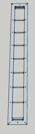
The panel is gone be a , mid high panel. with 0.5mm2 wires. outside diameter is 2 mm.
membrane suface is 408~ cm2 (6 cm x 68 cm) , stator spacing to membrane is 1mm, not sure yet if a wire stator is up to the task of these tight tolerances yet. but we will see.
outside dimensions are 72 x 10 , mebrane width is 6 cm. i forgot the right formula to know when beaming starts at this width have to look it up again, and again.
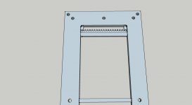
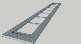
i first had holes to put the wire through at each end but this was verry time consuming, to do a whole frame. so i decided to make this teeth, so i can wind the wire while i suspend the frame on 2 blocks and a clamb in the midle of the frame to create a bow shape. when all wires are wounded hand tight, i realease the clamb's and they should be nice and stretched agains the supports. (theory)
before i release it, i put epoxy resin on all supports and the small space between the teeth section and the first support.
bolt it to a table and wait till its dry.
some picture of the design, im still waiting on a 2mm cutter for the teeth, and HPL plate high presure laminate. its verry stiff and machines well. each stator will be 6 mm thick. when its bolted together its pretty stif. nice thing to is HPL isolates pretty well and cheap, not as cheap as wood but much much stronger.
the 2 stators , after mebrane is attached and coated will be bolted together with the pre drilled holes. i also drill some extra holes for mounting the whole thing in a frame
after some hard work i finally have my diy CNC router machine workinghttp://www.youtube.com/watch?v=3fzRZKVsHFw&feature. so time to design a esl panel mid/high with wires. wich i can make over and over if needed.
im pretty new to the wire stators so if you see anything that could be better pls let me know, after all thats why we are here.
The panel is gone be a , mid high panel. with 0.5mm2 wires. outside diameter is 2 mm.
membrane suface is 408~ cm2 (6 cm x 68 cm) , stator spacing to membrane is 1mm, not sure yet if a wire stator is up to the task of these tight tolerances yet. but we will see.
outside dimensions are 72 x 10 , mebrane width is 6 cm. i forgot the right formula to know when beaming starts at this width
have to look it up again, and again.i first had holes to put the wire through at each end but this was verry time consuming, to do a whole frame. so i decided to make this teeth, so i can wind the wire while i suspend the frame on 2 blocks and a clamb in the midle of the frame to create a bow shape. when all wires are wounded hand tight, i realease the clamb's and they should be nice and stretched agains the supports. (theory)
before i release it, i put epoxy resin on all supports and the small space between the teeth section and the first support.
bolt it to a table and wait till its dry.
some picture of the design, im still waiting on a 2mm cutter for the teeth, and HPL plate high presure laminate. its verry stiff and machines well. each stator will be 6 mm thick. when its bolted together its pretty stif. nice thing to is HPL isolates pretty well and cheap, not as cheap as wood but much much stronger.
the 2 stators , after mebrane is attached and coated will be bolted together with the pre drilled holes. i also drill some extra holes for mounting the whole thing in a frame
Attachments
Last edited:
Typically the beaming starts when the width of the panel equals 1 wavelength and greater.
At 1 wavelength of width, the pattern transition's to a figure 8 pattern and gets narrower as the frequency gets raised.
Here are some simulations that I have done,
http://www.esldiy.com/esldiy/forum/index.php?topic=95.msg212#msg212
FWIW
jer
At 1 wavelength of width, the pattern transition's to a figure 8 pattern and gets narrower as the frequency gets raised.
Here are some simulations that I have done,
http://www.esldiy.com/esldiy/forum/index.php?topic=95.msg212#msg212
FWIW
jer
Last edited:
They are ESL's I am sure they will sound great!!!
I know my previous ones did, only they couldn't take the higher than normal voltages I was trying to apply, So I started a new design.
I have not finished those particular ones yet, But I don't anticipate any problems with them.
I will be getting to them very soon though.
Cheers!!!
jer
I know my previous ones did, only they couldn't take the higher than normal voltages I was trying to apply, So I started a new design.
I have not finished those particular ones yet, But I don't anticipate any problems with them.
I will be getting to them very soon though.
Cheers!!!
jer
ok then it start beaming on 5750 Hz, thats a bit to low for my likings. maybe i narrow it some more, or try sigmmentation, with a slightly larger panel.
Gerald verry nice picture in ur link. nice to see the actual effects.
i might try to sigment them in 2 sections, a fullrange 2 cm for 4K and up to 20K and the other till 4 k in conjunstion with the first makes 6 cm.
but ofc in have to find a balance in output. thought i had a simple spreadsheet for this somewhere.
33% open area is a bit tight!
I would shoot for no less than about 40% to 45% or so of open area.
FWIW
jer
well yeah most people have slightly more, but i have a pcb esl here from solosound wich has only 13% of open area, and it's stil sounds rather well.and is verry eficient.
the stupid thing is, allot of open area is taken by the insulator of the wire, im afraid to run out of force when i increase open area more.
having more ope area would made this allot easier to build
and i did not have to buy a new cutter i still might try it , and maybe with measurements we can finally put that question to rest.
Last edited:
33% may just give you the right amount of dampening as well.
You will have to give it a try.
Between the two models I have made using wire mesh one was in the 30% range and the other was in the 45% range and I like the larger open area better.
It sounded a bit less restricted and more...well.....Open if you will.
The first panel I made of the same exact size use some Perforated Alu. soffit stuff and the open area eneded up in the 20% to 25% range and there was a significant difference between that one and the last two.
Yes, the insulation thickness is a major factor and is why I choose to use a paint method as my rod diameter is .0625" (1.6mm) my overall dia. is about .078" to .080" (2mm) or so.
For reference here are the detailed specs in the second picture,
A Segmented Stator Desktop ESL
The wire to wire spacing is at .140" and the open spacing ended up around .058" this gives me about 41.4% open area.
jer
Last edited:
Hi,
a 3-D sketch most always looks well
The useability of this frame will depend on which wire You intend to use.
As the openeing between the ´teeth´ and the frames rim is so small even flexible stranded wire will be very difficult to wind.
How will You maintain even mechanical force/pull on the wire?
If the frame is somehow flexible You may bend the frame whilst winding, similar to the procedure of Acoustat.
If You intend to use single stranded wire this procedure won´t excert enough pull to straighten the wires. Too it´d probabely impossible at all to wind the wire around the teeth.
You would have to think at least about two issues.
1) Maybe leave the frame open at the top and bottom rim to allow for access to the teeth. And adding two braces in a following process that close the gap.
2) Thinking about a procedure to straighten the (single stranded) wire whilst the winding procedure, since the frame or the teeth themselves will hardly withstand the required pulling forces.
To achieve higher precision of wire positioning and to allow for less glue wetting more wire surface, I´d suggest a comb-like structure for the horizontal braces. Even better, each fork of the comb could already be designed such that the wires may press-fit in without the need for any glue at all. Besides the dry-mount beeing quicker and cleaner, it should be kept in mind that wire insulation may be tackled by glue solvents, which may lead to lower voltage breakdown limits and faster ageing.
As in the picture, I regard the frame model a first sketch of an idea. It requires refinement till production quality is reached.
jauu
Calvin
Thanks calvin, you mentioned à few things where we think alike
the wire is multiple strand wire, an is 2 mm thick the same size the teeth holes are.
I indeed want to hand tight the
In a jig to create a curved panel for winding. An indeed I will try
Mill a comb like thing in the support, 1,5 mm deep 2 mm wide. I am only worried that these small 1 mm thick teeth might break pretty easy when cutting. I thought about press fitting wire
I just have to get my hpl so I can make a test stator and learn. Eager to mill something usefull
- Status
- This old topic is closed. If you want to reopen this topic, contact a moderator using the "Report Post" button.
- Home
- Loudspeakers
- Planars & Exotics
- Designing easy to use wire stator. with HPL and a CNC router.