The scope showed 1Vp-p into primary. However, In thinking about it that should be 10V p-p as I had adjusted the output for the max I could get. I could not maintain 2Vp-p on the scope out beyond 400KHz and I suspect the scope was not detecting the 10X setting on the scope probes. I'll verify it tonight.
I measured the transformer on our old GenRad 1658 RLC bridge which was recently calibrated.
I got:
primary inductance - 1.05H
Leakage inductance - 5.02nH
capacitance primary to secondary 522pF
Lp is rather disappointing.
I measured the transformer on our old GenRad 1658 RLC bridge which was recently calibrated.
I got:
primary inductance - 1.05H
Leakage inductance - 5.02nH
capacitance primary to secondary 522pF
Lp is rather disappointing.
Last edited:
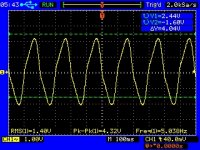
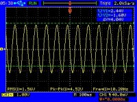
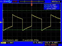
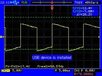
It was as I suspected, the scope does not detect the 10X probe and so the voltage was 20Vp-p in and 1.15Vp-p on the secondary loaded iwth a 330R resisstor.
Measuring with a 6.8K resistor in series with the primary and the secondary open, I get half the voltage across the transformer leads at 238 Hz for L of approximately 4.5H. Still not near what I expected.
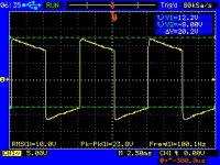
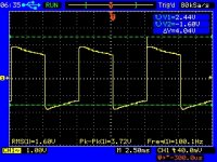
I ran a few tests again and captured the screens. Square wave does not show much as there is too much slope in the output of the signal generator.
Some of the peak in the original measurements was due to a peak in the signal generator. I'll have to go back and carefully adjust the input level and measure the output again.
Measuring with a 6.8K resistor in series with the primary and the secondary open, I get half the voltage across the transformer leads at 238 Hz for L of approximately 4.5H. Still not near what I expected.
I ran a few tests again and captured the screens. Square wave does not show much as there is too much slope in the output of the signal generator.
Some of the peak in the original measurements was due to a peak in the signal generator. I'll have to go back and carefully adjust the input level and measure the output again.
Attachments
Source resistance should be the same as in the actuall circuit.
Inductance in non gapped cores depends largely on the excitation voltage:
Bridges are useless here.
What will be a reasonable primary ac rms voltage when you are going to use it in your circuit?
Use the mains as a voltage source with a 6-7 KOhm resistor in series with the winding, adjusting the resistor value until you measure the desired V. across the primary.
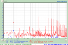
I measured around 4.7H using a resistor in series with the winding.
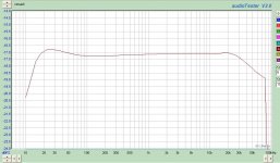
Out of curiosity I hooked it up to my sound card and ran a frequency sweep with a 520 ohm resistor across each output wired to the sound card differential input.
I got the attached curve running 24 bit 192Ksample rate.
The input to the transformer was -4db with a reference of 2.8Vrms as 0db.
It looks to me like it is +/-.3db from 20 to 20KHz. The hump at lf looks nasty, but I suspect it won't sound too bad.
Next up is to build the proposed amp and see how it sounds.
Attachments
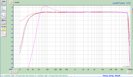
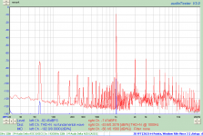
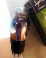
71A 6J9P Mu Follower Parafeed headphone amp
I built the output stage of my proposed headphone amp. It is a 71A Mu follower with Parafeed output. The top current source is a 6J9P.
I treid several coupling cap values starting with 1uF (orange trace) and working up till I got rid of the LF hump.
Frequency response looks pretty good with a 50uF film cap for coupling.
Attachments
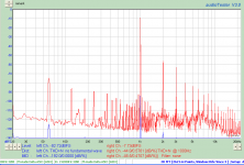
Looks like my sound card is toast.
1/2 channel is reading like I expect. The other 1-1/2 channels are really distorted.
Distortion now changes with bias conditions.
I still can't get distortion down where I think it should be. With 1.4Vrms out is is way higher than the simulations.
Of course the simulations could be way off too.
1/2 channel is reading like I expect. The other 1-1/2 channels are really distorted.
Distortion now changes with bias conditions.
I still can't get distortion down where I think it should be. With 1.4Vrms out is is way higher than the simulations.
Of course the simulations could be way off too.
Attachments
Time to fire up that old winding machine again.
I have two double C core mains transformers at the shelf waiting to be rewound as SE output transformers. To complicate things further I´ll make two transformers out of one, using half a core for each output tranny.
The goal is to make two nice pairs of OPT´s for the mid and high sections in my 4-way horn stacks.
The mains transformers seems to be the same brand but with different VA ratings so I must begin with making two different pairs of bobbins out of Pertinax sheets and glue.
Fortunately, as they are intended for mid and high frequency use only, I should be able to use thicker wire and fewer turns since there will be no need for high primary inductances.
I have to say you are starting with probably the most difficult audio trans to wind imho.
For good performance from interstage driver transformers, bi-filar windings are by far and away the best method to get good bandwidth, but you will need high quality double insulated wire, and v good winding technique to reduce risk of primary to secondary breakdown.
Best of luck
Yup, exactly. The Tango NC-20 is bifilar wound, like you mentioned. No interleaving required! Just calculate the primary winding inductance needed for your low frequency target. The way these transformers are hooked up in circuit is critical for their wide bandwidth. I know if the NC-20 is not hooked up in circuit like the paperwork suggests, its wide bandwidth goes out the window.
Daniel
I've started out by winding an output transformer with a 6:1 ratio for a headphone amp instead of starting with the inter-stage transformer.
The OPT turned out very well in that (1) it measures good from 5Hz to 100KHz in the intended circuit driving a 300R resistive load, and (2) it sounds good driving the intended load, which is a set of Sennheiser HD600 headphones.
I will probably build two more versions of this transformer with slight modifications for the final amp.
Before attempting the IT I will also rewind a bad SE transformer for a Magnavox 196 SE amp.
Do you have any suggestions with regards to winding format (unidirectional vs serpentine) and inter-layer insulation for the 1:1 inter-stage transformer?
TKS.
Steven
Hi Steven,
First to say, a fascinating thread. I too, have wanted to design and wind interstage transformers, finding your input very informative. For winding format, i took some hints from trafomatic's article on 6 moons. there seem to be a quite a number of sections, although this isn't for a 1:1 though. would it be for a single ended amp?
First to say, a fascinating thread. I too, have wanted to design and wind interstage transformers, finding your input very informative. For winding format, i took some hints from trafomatic's article on 6 moons. there seem to be a quite a number of sections, although this isn't for a 1:1 though. would it be for a single ended amp?
I got a jump on the transformers and wound the first bobbin last night. Initial tests without the core using a signal generator and voltmeter look good. Windings are much tighter than the first transformer so I expect greater coupling capacitance and upper f3 to be lower than the first one.
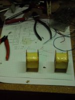
Coils Wound
I managed to get both coils wound this weekend.
The secondaries show different output voltages than calculated, and one is high while the other is low. This is true of both transformers and they match within less than 1%. So I went ahead and wired the output windings in parallel as planned, and they came in within 1% of the expected output.
Matching is better than 1% between the two coils when tested at 10KHz without cores installed.
Both show peaks around 110KHz.
I need to wire the leads and finish taping the coils before installing cores.
Attachments
- Status
- This old topic is closed. If you want to reopen this topic, contact a moderator using the "Report Post" button.
- Home
- Amplifiers
- Tubes / Valves
- Designing an Interstage Transformer