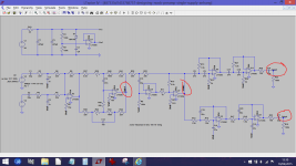
U6 and U7 look like an active volume control, phase correction for U9 and U10 perhaps.
that's the intention.
i think about rebuilding the Filter section with dual opamps.
so i can switch beween the three types in my stock NE5532, TL072, NJM2068.
i do Not have Tools many resistor values below 1k.
that might limit the choice if caps.
what causes that kind of noise?
are that opamps?
i used those before and never had problems like that.
not even on the cheap breadboard with long jumper wires and the psu 50cm away from the opamps.
not with trim pots for a variable xo frequency and that thing has two 24db filters (high and low cut) in each signal way.
that is weird to me.
i have changed the tl074 in the filter, the tl072 in the output inverter, the volume pot in the output (from 50k to 5k), crimped a new wire for the connection to the power amp....
nothing changes.
a slightly different filter on a breadboard in the exact same setup runs satisfying.
i still have the impression the same noise is audible from the output towards the woofer.
just not that significant, because it is cut by filter (and the lower sensitivity of the speaker).
A combination of the opamps and thermal or 'Johnson' noise from all resistive elements.
I found this for you,
Op Amp Noise and LTSpice
Solutions - LTspice IV: Noise Simulations
I found this for you,
Op Amp Noise and LTSpice
Solutions - LTspice IV: Noise Simulations
Mooly is doing a simulation. That will not consider good/bad layout.
The sim only considers the opamps and resistors for the various noise that come out.
I would guess that "noise gain" may be a clue to finding the problem parts of your circuits.
Remove or bypass all the not flat stages and bring them in one at a time.
The sim only considers the opamps and resistors for the various noise that come out.
I would guess that "noise gain" may be a clue to finding the problem parts of your circuits.
Remove or bypass all the not flat stages and bring them in one at a time.
Mooly is doing a simulation. That will not consider good/bad layout.
The sim only considers the opamps and resistors for the various noise that come out.
I would guess that "noise gain" may be a clue to finding the problem parts of your circuits.
Remove or bypass all the not flat stages and bring them in one at a time.
i did that and found the noise 'starts' in the crossover section.
One thing i found in the actual build that seems to be suboptimal is how ground to last 100k resistor at both outputs is wired.
it is more or less directly connected to the power supply ground of the last inverting opamp stage.
i'll change that.
but if that doesn't make a significant difference i completely rebuild that section.
"noise starts in the crossover section" means what?
that the crossover section is creating the excess noise and when this stage is bypassed the excess noise disappears?
yes, that is what i mean.
Then build just one half of the crossover and test it alone. no other filters, no other EQ, no active volume control, no summing stage, just the high pass cascaded B2 filters.
But, having seen Mooly's sim, you are wrong.
The noise shown in the sim does not originate in the crossover.
But, having seen Mooly's sim, you are wrong.
The noise shown in the sim does not originate in the crossover.
Last edited:
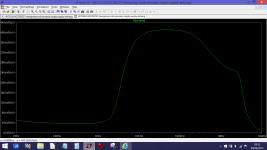
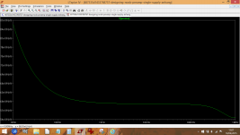
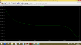
I've retested each section individually just by breaking the chain at stage and injecting the input signal at that point. So here you have four test points, Gain 1 through to Gain 4 and the noise of each stage. Look at the scale in Gain 1 plot. We are in microvolts of noise here.
Attachments
No the stages are not separated.
Pic 1 is relatively noisy. 0.7uVac/rootHz or 700nV/rootHz
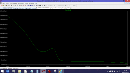
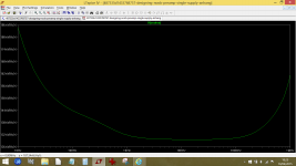
Pic 2 after passing all the preceding stages is noisy. 60nVac/rootHz.
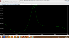
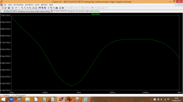
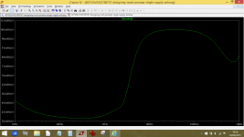
Pic 3 after passing through the high pass and the preceding stages attenuates some of the noise but leaves a narrow band with little attenuation. 21nV is -10dB of noise attenuation, 38nV is ~-5dB of noise attenuation.
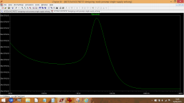
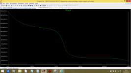
Pic 4 after passing through the low pass and the preceding stages attenuates some noise but leaves a narrow band with little attenuation.
It is clear that the EQ stages are introducing the noise and that the crossover is actually removing some of that noise, not generating it.
Pic 1 is relatively noisy. 0.7uVac/rootHz or 700nV/rootHz
Pic 2 after passing all the preceding stages is noisy. 60nVac/rootHz.
Pic 3 after passing through the high pass and the preceding stages attenuates some of the noise but leaves a narrow band with little attenuation. 21nV is -10dB of noise attenuation, 38nV is ~-5dB of noise attenuation.
Pic 4 after passing through the low pass and the preceding stages attenuates some noise but leaves a narrow band with little attenuation.
It is clear that the EQ stages are introducing the noise and that the crossover is actually removing some of that noise, not generating it.
Last edited:
Oh, then I was wrong in the way I read the post/pics.I did separate the stages for each test and then fed the input into each in turn.
The sim is on a different PC so I'll try the pots later.
It doesn't quite work like that ") You have to take the noise over the bandwidth of interest (say 10 to 20kHz) and then calculate it all back knowing the gain of the stage to derive a signal to noise figure for that stage.
You have to take the noise over the bandwidth of interest (say 10 to 20kHz) and then calculate it all back knowing the gain of the stage to derive a signal to noise figure for that stage.
Its not a quick job by any means for a filter like this.
You have to take the noise over the bandwidth of interest (say 10 to 20kHz) and then calculate it all back knowing the gain of the stage to derive a signal to noise figure for that stage. Its not a quick job by any means for a filter like this.
- Status
- This old topic is closed. If you want to reopen this topic, contact a moderator using the "Report Post" button.
- Home
- Source & Line
- Analog Line Level
- Designing a noob-preamp (single supply)