So one could connect two of these toroid (or any) xfmrs in series
You have to be careful how you wire the transformers in series. You can't use one transformer for each half of a P-P amp. It will see all of the DC current for one tube and thus be very unhappy. Don't ask me how I know this. You can use one half primary for each tube in series with the half primary from the other transformer. This can be carried to extreme. Stack up as many dual winding toroids (one winding per output tube) as you want with their primaries in series and wind one secondary through the cores of all of them at once.
I am currently trying some different tubes.
I had good luck with a pair of 6BQ6's and a power toroid out of a cash register. 30 watts was relatively easy to get, but there was some serious tube glow. The glow begins at about 12 to 15 watts with the B+ set at enough voltage to keep the distortion at 2%. The obvious thing to do is to use a bigger tube. I found out today that bigger is not always better. As I tried bigger and bigger tubes The glow point stays at about 12 to 15 watts, it just takes more B+ voltage to get enough current through the tube, which just raises its dissipation.
If big, wasn't better, how about small? I got some 6W6's for some hybrid experiments, so I decided to "sacrifice" a pair of wafer based Sylvanias. Surprise, the glow point is still 12 watts. I can get 12 watts at 190 volts of B+ with the 6W6 where I needed 400 volts to get 12 watts with the 6CB5's, and 250 volts with the 6BQ6's.
Did I say hybrid? While I have this toroid and the 6W6's hooked up, it would be easy to add some sand. I connected a pair of MJW21196 transistors to the 6W6's in "darlington" configuration. OK, this combination rocks. My poor power supply really didn't like this. I could get an easy 50 watts out of this setup with a B+ of 130 volts DC. My power supply wouldn't put out any more voltage than this. I measured the current drain and found it to be 650 mA. My power supply is rated for 300 mA. Again, I need more power supply.
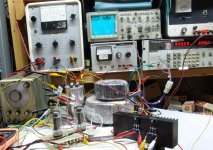
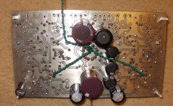
This picture shows the setup. The BIG toroid is the Plitron OPT. It is not connected in this test. The surplus power toroid is on top of it. The transistors are mounted on the heat sink on the right. It barely gets warm. Scope trace and analyzer readings are at 50 watts, 2% distortion. Note the pegged current meter on the Fluke PS.
I gave some thought to the suggestion of using 6146's for screen drive. I am not sure that they would be a good choice. A screen drive amp runs in near class B operation. The tubes draw very little current at idle, but the current rises quickly as the audio signal drives the tubes into conduction. Sweep tubes have a high peak cathode current capability. The 6146 has a maximum plate current spec of 135 ma. The peak cathode current is not specified. The little 6BQ6 has a 400 mA peak spec, the 6CB5 has a 770 mA spec, and the 6LW6 has a 1.4 AMP peak cathode current spec. Just look at the size difference in the cathodes themselves.
I don't have any 6146's here to test. I have some in the warehouse, so this is all conjecture at this point.
Attachments
The 6146B datasheet I looked at has the max current spec at 175 mA CCS spec or 220 mA ICAS spec. Maybe it's the difference (135 mA vs 175 mA) between the A,B versions.
http://www.mif.pg.gda.pl/homepages/frank/sheets/049/6/6146B.pdf
Comparing with a 6JN6, which uses 6.3V @ 1.2 A filament:
175 mA max DC and 550 mA peak
The 6146B runs at 6.3V @ 1.25 A filament:
175 mA max DC and ? peak
I would guess peak current has to be at least twice the 175 mA for linear operation, probably 550 mA like the 6JN6. The line voltage toroids, due to their primary Z limitations, certainly would be a better fit with the higher current HO tubes.
The line voltage toroids with dual primaries that I have measured have horrendous capacitance between the two primary windings, leading me to suspect they are wound near bifilar. That is why I was suggesting going with xfmrs with just one primary and series connecting several to get the hi Z and inductance required. (assumes decent insulation between primary and secondary to avoid capacitance problems there) One then necessarily has to operate them using SEPP or Circlotron mode since only one primary winding is available then. The asymmetric scheme I mentioned gets around the single winding limitation by using the secondary as a 2nd inverted primary winding as well as the secondary output.
Don
You are concerned too much of a primary inductance speaking of push-pull amplifiers. Power transformers are designed for up to 10 percent voltage loss on maximal power. The loss depending on frequency is more significant than primary inductance, anyway load resistance will prevail. However, for twice lower frequency on the same power a voltage has to be twice lower, so George's formula about 240V isolation transformer works well, but don't forget to reduce number of turns of the secondary so both windings will be equal.
"I was suggesting going with xfmrs with just one primary and series connecting several to get the hi Z and inductance required. (assumes decent insulation between primary and secondary to avoid capacitance problems there)"
I just measured a dual bobbin E-I xfmr (single 120V to 36V) and it has excessive leakage inductance. About 118 mHy. Putting two in series doubled that. 8x in series to get a decent primary L and V capability would 8x the leakage L to nearly a Henry. -NG-
I would think that winding a secondary onto an E-I isolation xfmr would have excessive leakage too. But a toroidal one may just work out fine if the secondary fully wraps the core. Presumeably the issue of capacitance between the 120V windings is handled well in a toroidal isolation xfmr., but I would check with a C meter.
Don
Antek does have some power transformers with dual 120 primaries, dual HV secondaries, and dual 6.3V windings - at $28 they're starting to get 'spensive though... at first glance, ratios seem a bit high, but if you added a bit more secondary in series with the two 6.3 windings....
6JN6/6GE5....
Its funny to see this thread just after Ive decided to 'clone' the Dave-Berning EA-230 screen-drive amp, but with a few changes of my own, like MOSFET drive to the final-tubes and a bit of other nonsense...
Whilst looking for the output bottles, the 6JN6 used in the original D.B. design is still reasonably cheap, but according to one of my suppliers has caught the interest of some guys. His entire stock of this tube has been wiped out just last week for 'amplifiers' he said......
As I have a mains Tx with 5 x 6V secondaries it makes no difference to me what the final-tubes heater volts is....
Both the 12JN6 and 17JN6 are identical to the 6JN6--apart from the obvious!-- but are generally half to a quarter the price...
And the other interesting thing Ive found by comparing the data sheets, is the 6GE5 has identical 'guts' the differences are in the pin-out and the fact the beam-plates are not internally connected on the 6JN6 and lead out separately, while they are in the 6GE6.
12GE6 and 17GE6 are currently just pennies, and the 12-pin sockets are not too pricey for new Chinese ceramic types either!
I Like Cheap!
---This could well be the cheapest amp I have ever made, I have some iron from a defunked Heathkit round here somewhere!--Happy days
I wonder what the most 'common' sweep-tube of this type (top-capless) is? Being based in the UK, there were only a handful of sweep-tubes to choose from while in the States, it seems you have hundreds of different types
Take a look at the 17KV6A on sale over at AES lately for $1.92. This is a similar tube but on a 9 pin Novar base (no plate cap) and rated at 28 Watts. Appear to be plenty available. The data sheet for it is lacking curves, but it's the same tube as 6KM6 which does have curves. (Look at the old 6KV6 non A data sheet, where it's rated at 80 mA, to be convinced that the two are indeed the same. Or use the formula gm = k I^.6666 for converting gm to different DC currents)
6JN6: gm 7300 at 65 mA or 8400 at 80 mA
rp 18K Ohm at 65 mA or 15K at 80 mA
Mu_triode 4.4 17.5 Watts
17KV6A/6KM6: gm 6000 at 40 mA or 9500 at 80 mA
rp 10K Ohm at 40 mA or 6K at 80 mA
Mu_triode 4.0 28 Watts/20 Watts
or there is the 31JS6C on sale for $3.50 30 Watts (has a plate cap)
and 25CD6 on sale for $1.10 20 Watts (has a plate cap)
There are some other capless Horizontal Output tubes around besides. 21JV6 21HB5A 31JV6
There is even an octal exact equivalent to the 6JN6 and it's capless too: 6FW5
Don
WOW!
SO many different types of line-output bottle (HO Tube...)
I guess it would be fair to say, there are at least ten different types for each base or socket type-eg, Octal, Magnovar, Duodekar etc.etc....
And, quite a few without top-caps too--just right for experimenting with!
Ive settled on the 12GE5 as Ive found some nice and cheap, and all the same make etc. --ordered 10--The supplier also carries the sockets at a reasonable price too.
Duodekar/Compactron types are pretty rare here in the UK. I can only think of one old make of TV set that used them, and that was 'Teleton'-an American import set of 14" screen, with its NTSC decoder modded somehow to work with PAL colour system--Always liked the 'Compactron' type of valve from my dealings with those sets. I seem to remember a Juke-box, Maybe a 'Seeburg' that used Compactron finals too, but have no idea what ones.....
I got some 6FW5's to try out since I already have some 6CB5A's with octal bases I bought cheap last week. Already have some 17JN6's, 12GE5's and 21JV6's. The bigger HO's (28Watt and above) are expensive due to CB/Ham rigs and whatnot. That 31JS6C (30 Watt) looks like quite a bargain at $3.50, but has a cap.
There are also some smaller HO / line -out tubes I forgot to mention: the 6AV5GA,12AV5GA are capless, and 6BQ6GA,12BQ6GA are equivalent but with caps. They are rated 11 Watts, but the GA versions of these seem to be the same plate size as the 6FW5 which is rated at 18 Watt.
If you have the GE Essential Characteristics tube book, there are too many HO tube types to count. Have to just go with whats on sale currently for cheap.
My first Heathkit Oscilloscope had compactrons in it, I've still got the schematic around somewhere. But unfortunately I sold it 30 years ago. Wish I still had it now. Looked just like a Tek. scope. Now I've got an old Tek. 7603.
Don
Such a contrast to Europe, where we only had a handful of capped HO tubes to choose from. Nearly all are 300mA heaters with voltages from 19 up to 40...
--And most that are 'Good' for audio and capless like the EL33 are just silly money....
For cheap (to keep the thread on track....) I believe you're right, Go with whats around and that seems to be the American tubes with all the variations...
I have an old Tek454 'scope complete with its Nuvistors--even managed too find a new CRT for it from a guy in New-York!
I started a PCB design that can use *JT6 or *GB5 tubes depending on a couple jumpers, both being 9 pin sockets. I contacted Edcor to see if they would be willing to make a custom heater tapped PT to use the 13, 17-18 and 21 volt heater tubes still available, i n process but no answer yet. Simple design with FET follower grid drive on the output tubes, can be bypassed and a few components left off...
PCB has B+, bias -70V and 6CG3 for slow start, again can be left off and bypassed.
What is a good Mosfet for the grid driver? IRF 710????????? I'm using the 160 volt for the upper rail and -70volt for the bottom rail for it, DC coupled to the gate, that should be good for +-60volt swing....
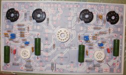
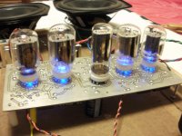
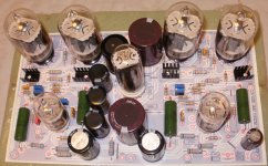
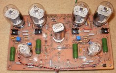
Thinking that with 17watt dissipation, 400V and 45ma on the bias, that keeps the caps single and not stacked keeping the cost down. I did this same concept on a Quad Spud'ed 6LU8 amp that I've been playing with, sounds great with 6.6k Bogen iron. I etched it with the copper side up, to have the bias pots on the bottom side to minimize the holes in the top plate. The pics are from the initial fire-up to see if the "magic smoke genie" would appear.
PCB has B+, bias -70V and 6CG3 for slow start, again can be left off and bypassed.
What is a good Mosfet for the grid driver? IRF 710????????? I'm using the 160 volt for the upper rail and -70volt for the bottom rail for it, DC coupled to the gate, that should be good for +-60volt swing....Thinking that with 17watt dissipation, 400V and 45ma on the bias, that keeps the caps single and not stacked keeping the cost down. I did this same concept on a Quad Spud'ed 6LU8 amp that I've been playing with, sounds great with 6.6k Bogen iron. I etched it with the copper side up, to have the bias pots on the bottom side to minimize the holes in the top plate. The pics are from the initial fire-up to see if the "magic smoke genie" would appear.
Attachments
Last edited:
Cheap PP Power Amp.
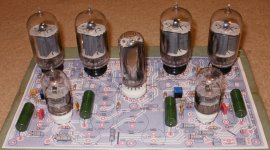
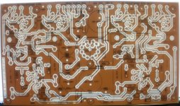
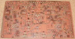
Still scrounging components, but have it etched and ready to tin plate the back side prior to the drilling marathon. For Mosfets, I found some K2700 to play with. They are electrically isolated at the tab for easy mounting. I'm sure that they will not be able to transfer heat as well, but they are not that stressed, should not require it.
I left another message at Edcor to see if they are interested in winding a custom heater PT, 6.3, 13, 17.5 and 21 VAC for the weird ones. They have the tinker box series that is close, just need to add the B+ and bias and change the heater targets.
I have a couple flats of 17JT6 tubes to play with and can use a 18VCT short term to supplement a "normal" 6.3VCT heater PT. I also have some 18GB5 tubes to try.....
The B+ is targeted to be 400V so 450V caps can be used. The 6GC3 is for slow B+ start. and for those that don't care, it can be left out and jumper-ed. The output tubes are setup for Mosfet grid drive, again can be left out and jumper-ed if not wanted... but I like the idea of reducing the possibility of blocking distortion when driven hard.
I have a set of 40watt 6.6KRaa Hammonds for outputs, old style without the UL taps. I'll configure in Pentode mode first and compare against the 6LU8 PP amp in the previous post. It has been the daily driver for a couple months. A very sweet amp, maybe due to the Bogen output iron.
Attachments
I designed an 80 watt quad el34 valve amplifier.
It has a twin gain stage on the front end into a tone control, another gain stage then a phase splitter before the quad el34 output stage.
Sounds very nice and detailed.
Not enough distortion for my guitar though.
Suits use with an mp3 or cd player best.
It has a twin gain stage on the front end into a tone control, another gain stage then a phase splitter before the quad el34 output stage.
Sounds very nice and detailed.
Not enough distortion for my guitar though.
Suits use with an mp3 or cd player best.
An externally hosted image should be here but it was not working when we last tested it.
Cheap PP Power Amp.
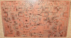
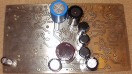
Still need to drill/elongate tube holes/slots for output and 6CG3 tube sockets. All eyelets installed for functional feed throughs for heavy wires and caps on the back side. Quick spacing check verifies the mock-up worked for confirmation for fit.. If I need to, the PIO coupling caps can also go on the back side.
I've placed an order for the sockets, so I should be able to complete the drilling and start the soldering marathon soon. I found a 18Vct 5Amp filament transformer to supplement the 300VAC B+ iron for the 17JT6 flavor. Still a few more components to scrounge.......
Attachments
Last edited:
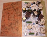
I use shorting leads across the Mosfets, they will be pulled prior to firing up. Started the heater wiring for the 6volt section, I will complete the 17Volt section after installing ceramic sockets for the outputs. I have some for Magnovar sockets but they are designed for pins that are 0.010" bigger in Dia so there is not enough interference with the 0.036" dia. pins.
I'm looking at an Edcor PT, their XPWR247, 330-0-330, two windings 6.3V@4A and two windings 5V@4A. That would allow for a combination of 6.3 +two 5volt to make a 16.3V at 4 Amp that could power the output tubes and would leave a 6.3 at 4Amp for the input an damper diode. The 16.8 volt heaters would be operating at 3% below nominal which is acceptable. The B+ would be pushing 480V near the limit for the caps. The damper diode will drop voltage and so will the choke, may have to add a resistor or extra CL80.
I'm looking at an Edcor PT, their XPWR247, 330-0-330, two windings 6.3V@4A and two windings 5V@4A. That would allow for a combination of 6.3 +two 5volt to make a 16.3V at 4 Amp that could power the output tubes and would leave a 6.3 at 4Amp for the input an damper diode. The 16.8 volt heaters would be operating at 3% below nominal which is acceptable. The B+ would be pushing 480V near the limit for the caps. The damper diode will drop voltage and so will the choke, may have to add a resistor or extra CL80.
Attachments
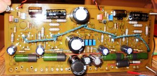
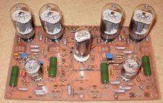
Finished stuffing and did the initial fire-up. I used a Hammond 300-70-0-300 PT with a separate 18V filament PT just for the output tubes.
Replaced the 6.8K 2 watt with a power 100V zener, 100v zener, mosfet and heatsink, the 6.8K was too warm dropping from 400 to 300 volts. The 300V also supplies the 160V supply for the mosfet drive circuit and 250V first stage.
The rest are OK and initial bias adjustment was set to -36volts. The 17JT6 should should be throttled at that initial bias. I'l use 6.6K 40 watt Hammonds, I have an old style set without the UL taps.
- Status
- This old topic is closed. If you want to reopen this topic, contact a moderator using the "Report Post" button.
- Home
- Amplifiers
- Tubes / Valves
- Designing a "cheap" highish-power PP amp...