Inspired by your design I drew a 4-folded horn with the original configuration of the driver being at the rear end.
So step by step what I did:
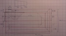
1. Calculate L12 + L23 + L34 for total length: 290.5cm
2. Divide by four: 72.6cm (four folds)
3. Set width of the Enclosure to 35cm
4. Calculate the height of S1 to S4
5. Calculate (S2 + S3) * 2 to get the total height: (14cm + 5.1cm) * 2 = 38.2cm
6. Draw the border of 38.2cm * 72.6cm
7. Calculate the height at 1/4, 1/2 and 3/4 length, Q2: 12.1cm; Q3: 9.7cm; Q4: 7.2cm
8. Draw the segments(?) and use the 45° method to cut them
9. Draw the driver at L12
10. Draw the opening at a distance of L34 from the middle poit in front of the membrane
The drawing has a scale of 2mm to 1cm.
The outer radius of the driver is 31.5 cm so L12 has to be adjusted otherwise it won't fit.
So is this correct how I did it?
cheers!
hurtz
So step by step what I did:
1. Calculate L12 + L23 + L34 for total length: 290.5cm
2. Divide by four: 72.6cm (four folds)
3. Set width of the Enclosure to 35cm
4. Calculate the height of S1 to S4
5. Calculate (S2 + S3) * 2 to get the total height: (14cm + 5.1cm) * 2 = 38.2cm
6. Draw the border of 38.2cm * 72.6cm
7. Calculate the height at 1/4, 1/2 and 3/4 length, Q2: 12.1cm; Q3: 9.7cm; Q4: 7.2cm
8. Draw the segments(?) and use the 45° method to cut them
9. Draw the driver at L12
10. Draw the opening at a distance of L34 from the middle poit in front of the membrane
The drawing has a scale of 2mm to 1cm.
The outer radius of the driver is 31.5 cm so L12 has to be adjusted otherwise it won't fit.
So is this correct how I did it?
cheers!
hurtz
Attachments
Inspired by your design I drew a 4-folded horn with the original configuration of the driver being at the rear end.
So step by step what I did:
1. Calculate L12 + L23 + L34 for total length: 290.5cm
2. Divide by four: 72.6cm (four folds)
3. Set width of the Enclosure to 35cm
4. Calculate the height of S1 to S4
5. Calculate (S2 + S3) * 2 to get the total height: (14cm + 5.1cm) * 2 = 38.2cm
6. Draw the border of 38.2cm * 72.6cm
7. Calculate the height at 1/4, 1/2 and 3/4 length, Q2: 12.1cm; Q3: 9.7cm; Q4: 7.2cm
8. Draw the segments(?) and use the 45° method to cut them
9. Draw the driver at L12
10. Draw the opening at a distance of L34 from the middle poit in front of the membrane
The drawing has a scale of 2mm to 1cm.
The outer radius of the driver is 31.5 cm so L12 has to be adjusted otherwise it won't fit.
So is this correct how I did it?
cheers!
hurtz
Hi hurtz,
Good job..Looks OK..The physical total internal box height would be calculated as:
(L12+L23+(not L34 ) but L12(again))/4 as L12 is longer than for the airways necessary L34= 10 cm.
b
")
I've adjusted L12 to 18cm so the driver actually fits now.
Still with wood the enclosure will be about 80cm tall which is about 15cm too much. So either the sub will have its opening facing upwards at the 20cm distant desktop, or lying on the side, forwards into the room at the 1,6m distant wall.. any thoughts about this?
I've just started drawing the enclosure with cad program (which is a real pain) and will submit pictures and data shortly.
cheers!
hurtz
I've adjusted L12 to 18cm so the driver actually fits now.
I too noticed that L12 was short of 5mm but didn't recognize this fact until I already had posted the simulation.
When I build subs: I'm very used to countersink the frame/ or magnet of a speaker driver in order to minimize the with or depth and if only short of a couple of mm:s, as for your case =2,5 mm on both sides of the frame I let you or any other DIYaudio member to discover this issue.
Still with wood the enclosure will be about 80cm tall which is about 15cm too much. So either the sub will have its opening facing upwards at the 20cm distant desktop, or lying on the side, forwards into the room at the 1,6m distant wall.. any thoughts about this?
I wouldn't face the sub upwards if the driver cone is overtime prone to be sagging.
The sub is omni and IME very easy to integrate with the main speakers and if you have built this sturdy with cross-bracings and by using properly filters to define the BW: You will not get any localization cues almost wherever you place this T-TQWT in your room.
b
Done and done
I did the technical drawing with libredraw which went much better than expected and bought all the parts. The enclosure will be made from 18mm MDF now.
Only very few questions left until final subwoofer ;-)
1. is the shape of the S4 important? I've seen rectangular shapes covering the whole width of the box and round ones. Is it ok to use a rectangular hole that doesn't cover the whole width of the box(airway)?
2. In your first simulation, (i.e. the ttqwt I'm building right now) is it correct that you used a 80Hz LP-4th-LWR and a 25Hz HP-butterworth?
Question is, why use a butterworth instead of LWR?
cheers!
hurtz
..Only very few questions left until final subwoofer ;-)
1. is the shape of the S4 important? I've seen rectangular shapes covering the whole width of the box and round ones. Is it ok to use a rectangular hole that doesn't cover the whole width of the box(airway)?
2. In your first simulation, (i.e. the ttqwt I'm building right now) is it correct that you used a 80Hz LP-4th-LWR and a 25Hz HP-butterworth?
Question is, why use a butterworth instead of LWR?..
Hi,
I've tried almost all shapes there is and by far noisiest is the Carlsson slot type at high cone excursions if made smaller than Sd/3 and covering the whole enclosure width and exceeding the length of a normal size access lid.
I think the limit for aspect ratio is as it would be if not moving the original HR S4.
Moving this port 90 degree to the bottom of the enclosure worked equally well and the difference in FR is minimal.
Best aspect ratio for a rectangular port is when less than 3/1 or completely circular.
It's better to use a Bw4 HP filter at 25 Hz than LR4 type in order to preserve(maximize) usable BW or (equal to) a LR4 HPF if the sub-amp has a low end boost facility set to +3dB at the filter cut-off..
A LR4 HPF has more in-band interaction with the LPF when a small BW is used.
b
Attachments
Hi,
Happy new year to you!
Ok, only active filters are left and I think I'm done.
As I understand it the basic setup is:
input buffer -> LR4 -> BW4 -> amp
The input buffer schematic I'd take from here: Linkwitz-Riley Electronic Crossover (Figure 3)
The LR4 also from Rod Elliot's LR4 calculator.
The BW4 however I'm still a bit confused about. This project: Subsonic / Rumble Filter for Phono preamps and Sub-Woofers uses a BW4, but with the added capacitor (C1/C4) I think it is called a 3-pole filter as opposed to the 2-pole filter where it is left out. Is the "2-pole" the same as the 2nd order? Then this would be a 6th order HP. Also it should be simple to reduce it to a 4th order by simply removind the CAPs C1 and C4.
Also is it possible to use the 120nF/22.7Hz cutoff (sorry still can't simulate for lack of windows)? The Design seems to be very well thought through and I don't feel like reinventing the wheel worse...
cheers!
hurtz
Hi,
Happy new year to you!
Ok, only active filters are left and I think I'm done.
As I understand it the basic setup is:
input buffer -> LR4 -> BW4 -> amp
The input buffer schematic I'd take from here: Linkwitz-Riley Electronic Crossover (Figure 3)
The LR4 also from Rod Elliot's LR4 calculator.
The BW4 however I'm still a bit confused about. This project: Subsonic / Rumble Filter for Phono preamps and Sub-Woofers uses a BW4, but with the added capacitor (C1/C4) I think it is called a 3-pole filter as opposed to the 2-pole filter where it is left out. Is the "2-pole" the same as the 2nd order? Then this would be a 6th order HP. Also it should be simple to reduce it to a 4th order by simply removind the CAPs C1 and C4.
Also is it possible to use the 120nF/22.7Hz cutoff (sorry still can't simulate for lack of windows)? The Design seems to be very well thought through and I don't feel like reinventing the wheel worse...
cheers!
hurtz
Hi hurtz,
Good work..Why not download an easy to use simple filter-designer that also uses standard components like the one here:
b
Attachments
Hi again,
so some time passed and the subwoofer is finally finished
The sound is good, and I'm very happy with it. Since I have nothing to compare it to I can only say that it covers its targeted frequency range quite nicely.
The active crossover is still missing at this point since I do the filtering directly in mplayer (linux media player)
Concerning the cost of the whole thing:
Chassis: 50€
Wood: 40€
Paint: 15€
Terminals+internal cables+damping+screws: 18€
Acryl: 7€
--------
Total: ~140€
Not exactly under 100€ but close enough. This is of course minus the active crossover and Amplifier. (wich should be around 60€ together)
Many thanks to you bjorno for helping me with this great project!
cheers!
hurtz
- Status
- This old topic is closed. If you want to reopen this topic, contact a moderator using the "Report Post" button.
- Home
- Loudspeakers
- Subwoofers
- Design check of a simple <100€ sub