Hi Everyone,
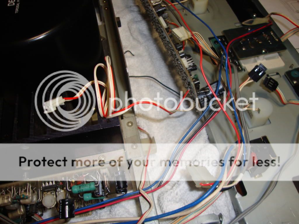
last night while listen to Bill Evans, My Left Channel went out. I turn it off, Removed it from my rack, took the Covers off and just when I plug it in (Smoke) Which I didn't get to see since My kids came down stair wondering why the hell I turned off the music. Timing I tell you...I'm Pretty Positive it came from the Sp Unit:
http://i1223.photobucket.com/albums/dd513/Migkiller1971/DSC00769.jpg
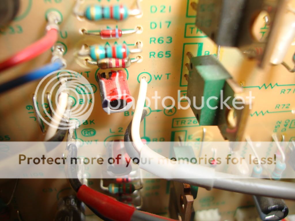
I took the speaker binding off the the board and on a closer view, It's obvious that this board is cracked and the previous owner did what he could to fix it. Its cracked precisely where the Left Channel relay(?) is connected to the board:
http://i1223.photobucket.com/albums/dd513/Migkiller1971/DSC00783.jpg
http://i1223.photobucket.com/albums/dd513/Migkiller1971/DSC00790.jpg
http://i1223.photobucket.com/albums/dd513/Migkiller1971/DSC00780.jpg
Of course this unit is at least 20 years old, So parts are going to be hard to come by. I need a recommendation on substitute Relays? The resistors, Caps, Connectors and parts should be no problem.
http://i1223.photobucket.com/albums/dd513/Migkiller1971/DSC00798.jpg
The another thing is.... The PCB Board. Can I salvage it by Soldering the hell out of it even more or I've seen youtube Clips on how to make your own PCB Board. Its pretty straight forward but I don't have the Software. Is there anyone on here who can probably print it out for me? Thank you and Happy Holidays..
last night while listen to Bill Evans, My Left Channel went out. I turn it off, Removed it from my rack, took the Covers off and just when I plug it in (Smoke) Which I didn't get to see since My kids came down stair wondering why the hell I turned off the music. Timing I tell you...I'm Pretty Positive it came from the Sp Unit:
http://i1223.photobucket.com/albums/dd513/Migkiller1971/DSC00769.jpg
I took the speaker binding off the the board and on a closer view, It's obvious that this board is cracked and the previous owner did what he could to fix it. Its cracked precisely where the Left Channel relay(?) is connected to the board:
http://i1223.photobucket.com/albums/dd513/Migkiller1971/DSC00783.jpg
http://i1223.photobucket.com/albums/dd513/Migkiller1971/DSC00790.jpg
http://i1223.photobucket.com/albums/dd513/Migkiller1971/DSC00780.jpg
Of course this unit is at least 20 years old, So parts are going to be hard to come by. I need a recommendation on substitute Relays? The resistors, Caps, Connectors and parts should be no problem.
http://i1223.photobucket.com/albums/dd513/Migkiller1971/DSC00798.jpg
The another thing is.... The PCB Board. Can I salvage it by Soldering the hell out of it even more or I've seen youtube Clips on how to make your own PCB Board. Its pretty straight forward but I don't have the Software. Is there anyone on here who can probably print it out for me? Thank you and Happy Holidays..
i would make a new board.
if you make a scematic.
take lots of pictures... and then remove the components, clean all the extra solder off the board and through holes, clean well in a solvent. ive had luck just putting boards on a scanner and coping them using a laserprinter. iron that on the new board and etch.
if you need to modifiy for diffrent parts a sharpie works good.
i would see first what went belly up in the channel first. chances are that somthing from the output went bad to cause this.
just as info some solder wick placed neatly works alot better than globs of solder to fix this kinda stuff. i know it wasnt you but.....if it ever comes to you doing this...mental note
i would make a new board.
if you make a scematic.
take lots of pictures... and then remove the components, clean all the extra solder off the board and through holes, clean well in a solvent. ive had luck just putting boards on a scanner and coping them using a laserprinter. iron that on the new board and etch.
if you need to modifiy for diffrent parts a sharpie works good.
i would see first what went belly up in the channel first. chances are that somthing from the output went bad to cause this.
just as info some solder wick placed neatly works alot better than globs of solder to fix this kinda stuff. i know it wasnt you but.....if it ever comes to you doing this...mental note
Yeah, I was kind of pissed when I saw that solder work. Never thought about scanning it. I have the Schematics. I have to go hunting and see what went wrong.
Thanks!
I Did find this:
http://i1223.photobucket.com/albums/dd513/Migkiller1971/DSC00826.jpg
http://i1223.photobucket.com/albums/dd513/Migkiller1971/DSC00827.jpg
I guess I have to remove it to test it?
http://i1223.photobucket.com/albums/dd513/Migkiller1971/DSC00826.jpg
http://i1223.photobucket.com/albums/dd513/Migkiller1971/DSC00827.jpg
I guess I have to remove it to test it?
I have everything coming in for a new PCB board. The schematics calls for (2):
.022UF 5% 630v Metallized Plastic Film Capacitors but Can't find them on mouser or Digikey. Is there another term I should be looking for?
thanks.
http://i1223.photobucket.com/albums/...1/DSC00798.jpg
.022UF 5% 630v Metallized Plastic Film Capacitors but Can't find them on mouser or Digikey. Is there another term I should be looking for?
thanks.
http://i1223.photobucket.com/albums/...1/DSC00798.jpg
mig...
first off post #4: you will proably have to remove it to test it, but you will definatly have to to replace it.
post#5: 22nf film cap like newark part# 32R8853 from newark.com would work. might plan on changing the ones in the other channel also???? i dont know might change the sound considring its looks like its part of the LC on the output. someone else might be able to tell u more.
post#6: if it is a coil with shrink tube on it, and it got hot enough to shrink the tube more to split it. it might be ok.take it out,allong with one of the other ones of the same value and ohm it out.
i might have that scematic but just incase... can you post it?
off the top of my head i would say that some of the semiconductors in the output went bad and shorted. giving rail voltage where it shouldnt have been. i would plan on changing most if not all of the semi's in that channel. if you cant find replacements you can use alldatasheet.com to get the values and search from there. not the end of the world, plus you can tweek it also.
might be a good time to make both channels better.
so...where you a fighter pilot?
mig...
first off post #4: you will proably have to remove it to test it, but you will definatly have to to replace it.
post#5: 22nf film cap like newark part# 32R8853 from newark.com would work. might plan on changing the ones in the other channel also???? i dont know might change the sound considring its looks like its part of the LC on the output. someone else might be able to tell u more.
post#6: if it is a coil with shrink tube on it, and it got hot enough to shrink the tube more to split it. it might be ok.take it out,allong with one of the other ones of the same value and ohm it out.
i might have that scematic but just incase... can you post it?
off the top of my head i would say that some of the semiconductors in the output went bad and shorted. giving rail voltage where it shouldnt have been. i would plan on changing most if not all of the semi's in that channel. if you cant find replacements you can use alldatasheet.com to get the values and search from there. not the end of the world, plus you can tweek it also.
might be a good time to make both channels better.
so...where you a fighter pilot?
Hi Scott,
Thanks for the help. Yes I have a schematic, I'll post it up or send it to you. I just finished modding up my phono preamp and bang. 2 hours of listening pleasure..What a sweet sounding amp.
I barely touch that transistor and it came apart. Both channel feed into that Sp unit with the 22nf caps. I'll test it. I might as well change that inductor. Looks weird. like a clown in there. I'm going to replace all the caps also. Thanks for that alldatasheet. That will come in handy!!
so...where you a fighter pilot?
I was feared in the skies of Deutschland!!! I used to play tons of simulation flight games when I was younger. The name just stuck and my kid is the "migkiller" in xbox360 live..
Last edited:
ok send or post..if you post more help might be avaliable. most guys around here have forgot more than i know.
never fails when its sounds the best it gose bad.
ive always liked denon. i still use them as my home theater pre/pro. and i recomend them to any one who is in the market .
and i get the migfighter now.
by the way i cant spell and the spell check dosent work on my phone
never fails when its sounds the best it gose bad.
ive always liked denon. i still use them as my home theater pre/pro. and i recomend them to any one who is in the market .
and i get the migfighter now.
by the way i cant spell and the spell check dosent work on my phone
Last edited:
ok send or post..if you post more help might be avaliable. most guys around here have forgot more than i know.
never fails when its sounds the best it gose bad.
ive always liked denon. i still use them as my home theater pre/pro. and i recomend them to any one who is in the market .
and i get the migfighter now.
by the way i cant spell and the spell check dosent work on my phone
Denon POA 1500:
denon_poa-1500_[ET].pdf
Right Now I'm using a backup sony tan330es until I get this denon up.
Thanks for all the help!!
The more I dig into this amp, the more I get fustrated. Now I'm by far far no expert and haven't read a schematic in 20 years until acouple of weeks ago when I modded my phono preamp but this is what I just noticed: Call me crazy but this doesn't look right?

goes to:
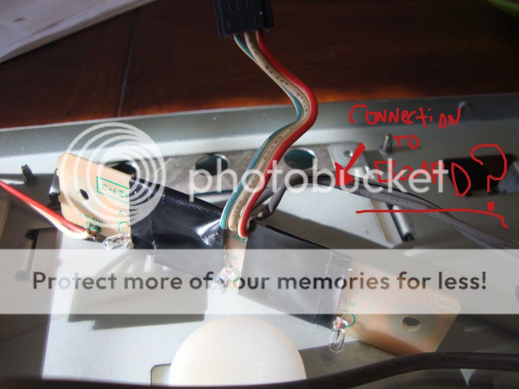
Now, these amps are notorious for the lamps to go out. It took me 2 minutes to find a denon service bulletin for this:
1. change TR 35 & TR 36 from 2SC1815 to 2SC2655
2. changed lamps from 28v / 40mA to 28v / 60mA
3. Change Resistors R101 & R102 from 15K to 4.7K
Wham. Done. Why would someone do this? Can this powersource going to the lamp board plus having the board plugged in to the control board cause problems? Even if you couldn't find these parts or lamps. Would soldering in a Resistor at the lamp board power up a LED? I need a smoke!!!
goes to:
Now, these amps are notorious for the lamps to go out. It took me 2 minutes to find a denon service bulletin for this:
1. change TR 35 & TR 36 from 2SC1815 to 2SC2655
2. changed lamps from 28v / 40mA to 28v / 60mA
3. Change Resistors R101 & R102 from 15K to 4.7K
Wham. Done. Why would someone do this? Can this powersource going to the lamp board plus having the board plugged in to the control board cause problems? Even if you couldn't find these parts or lamps. Would soldering in a Resistor at the lamp board power up a LED?
I need a smoke!!!well i cant say why they did it .... i just glanced at the print. q26 looks like if it shorted it would put the output to ground.. i think. i just looked at it breifly. im going to have to print it out and tape it together to look at it right.
wait so someone added a secpnd power source to the lamp board by adding a resistor to b+ and ground?
and you have replaced theses per service bilitin?
have you removed these wires?
wait so someone added a secpnd power source to the lamp board by adding a resistor to b+ and ground?
and you have replaced theses per service bilitin?
have you removed these wires?
well i cant say why they did it .... i just glanced at the print. q26 looks like if it shorted it would put the output to ground.. i think. i just looked at it breifly. im going to have to print it out and tape it together to look at it right.
wait so someone added a secpnd power source to the lamp board by adding a resistor to b+ and ground?
and you have replaced theses per service bilitin?
have you removed these wires?
I haven't touched anything yet. I'm waiting for parts and caps to come in. I'M just digesting this in right now. I won't mess with anything until I get most of it in. That way I can keep track. I still have to order the semiconductors to went and anything I missed. Yes, there is a second power source coming straight in from b+ and ground "NO RESISTOR"..I have not done the bulletin upgrade. Maybe I'm wrong but that doesn't seem right to me.
Last edited:
Hi Everyone,
The another thing is.... The PCB Board. Can I salvage it by Soldering the hell out of it even more or I've seen youtube Clips on how to make your own PCB Board. Its pretty straight forward but I don't have the Software. Is there anyone on here who can probably print it out for me? Thank you and Happy Holidays..
If I have a cracked pcb I solder a single core solid wire to the tracks.
This gives it more strength than just solder.
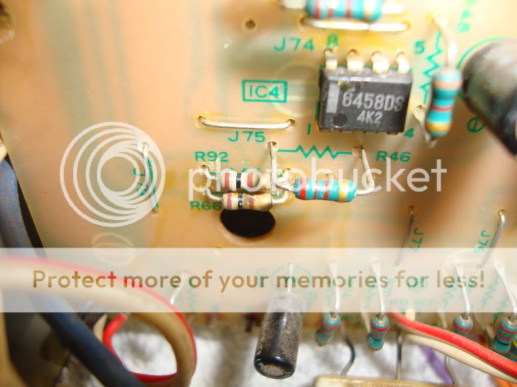
ok the trouble makes sence now i looked a bit more(still havent printed) but if you look at your scematic q26 if it shorts to ground your output relay will not pick and all the current will try to go through most of the resitors you have posted as burnt. i cant find 66 but i might be blind. that would make that little transistor turning to dust a good clue.
are you unsure of the bulitin or why he added the second b+/Grnd? i dont know why the added b+ either
their bullitin sounds like they beefed it up a bit. higher current in that part of the cir.
if that is the case.
it might be easer to fix.
i would start one by one checking the simi's that are attached to the base/15k res off of tr36 and tr37. 36 and 37, those look like they light the bulbs behind the meters right?
you know i bet whoever did this "repair" lost the cir path to ground to light the bulbs....and didnt know why other than it didnt have B+/G at the bulbs so to fix it they found another power source. the transistors might have been shot when you got it and it shorted later. or
they burnt up bufor you got it and the "repair" made it light up and work untill a new problem arived.
what would you think about pulling the relays and isolating the protect cir and see if the output of the amp is ok? if that sound like somthing you want to try maybe we can both look at this a section at a time. thoughts?
post #4 second pick.... where do the red and white wire go?
also please note how far the red wire is stripped and how close it is to other traces might be bad.
did the protect lights come on or just no sound and later smoke fizzle?
I was just looking at that. I have no idea where that red/white goes. I don't remember pullingit off. I looked at the Connection schematic and could not find it. Another attempt to bypass or fix something?
ok the trouble makes sence now i looked a bit more(still havent printed) but if you look at your scematic q26 if it shorts to ground your output relay will not pick and all the current will try to go through most of the resitors you have posted as burnt. i cant find 66 but i might be blind. that would make that little transistor turning to dust a good clue.
are you unsure of the bulitin or why he added the second b+/Grnd? i dont know why the added b+ either
their bullitin sounds like they beefed it up a bit. higher current in that part of the cir.
if that is the case.
it might be easer to fix.
i would start one by one checking the simi's that are attached to the base/15k res off of tr36 and tr37. 36 and 37, those look like they light the bulbs behind the meters right?
you know i bet whoever did this "repair" lost the cir path to ground to light the bulbs....and didnt know why other than it didnt have B+/G at the bulbs so to fix it they found another power source. the transistors might have been shot when you got it and it shorted later. or
they burnt up bufor you got it and the "repair" made it light up and work untill a new problem arived.
what would you think about pulling the relays and isolating the protect cir and see if the output of the amp is ok? if that sound like somthing you want to try maybe we can both look at this a section at a time. thoughts?
R66 is the last resistor before TP2 output (to speaker?) I think. its on page 9.. I don't know if the Bulletin was done. The reason I bought that up was because I found LED lights in the lamps and than that wire to B+ supply. The other possibility is that someone did do the bulletin and someone else bypass it.
what would you think about pulling the relays and isolating the protect cir and see if the output of the amp is ok? if that sound like somthing you want to try maybe we can both look at this a section at a time. thoughts?
Cool. I can keep up but I need a little instruction.
Its been a really bad week. I just received a bad pressing on vinyl of John Coltrane Giant steps. Man I thought it was supposed to be Christmas!!!
http://www.youtube.com/watch?v=pgq-lpJcOzw
Last edited:
post #4 did the protect lights come on or just no sound and later smoke fizzle?
No It did not come on. My left channel just turned off. I stop playing the vinyl and replaced a tube in my preamp because I thought it might have gone bad. I'm pretty sure smoke fizzle came up by the SP Unit.
- Status
- This old topic is closed. If you want to reopen this topic, contact a moderator using the "Report Post" button.
- Home
- Amplifiers
- Solid State
- Denon Poa 1500 Help.. Advice......