The thoughts below may be completely wrong...
It does look like (to me) TPC loads the VAS output more but could this be negated by moving the TPC connection to the next stage (eg. drivers or pre drivers). But this may well require extra compensation as TPC compensation now encloses more transistors? And then the advantage of moving the TPC "take off point" may be reduced?
I still need to think more about some of the content but you may want to look at THIS SITE where similar ideas are discussed.
Best wishes
David
Last edited:
The thoughts below may be completely wrong...
It does look like (to me) TPC loads the VAS output more but could this be negated by moving the TPC connection to the next stage (eg. drivers or pre drivers). But this may well require extra compensation as TPC compensation now encloses more transistors? And then the advantage of moving the TPC "take off point" may be reduced?
Hi,
Moving the take off point of TPC (two pole compensation)
is TMC (transitional miller compensation). An advantage
of TMC is it reduces the loading of the VAS of TPC by
effectively "bootstrapping" the compensation resistor.
By an order of magnitude according to DZ's link.
If your going to move it you may as well enclose
the whole output stage. Note that both arrangements
revert to single pole on the VAS only at higher frequencies.
rgds, sreten.
Last edited:
TIS: Transimpedance stage; also erroneously called the "VAS".
TAS: Transadmittance stage; also known as the input stage.
Anything else?
Thanks but those two were defined in post #1.
How about TPC and TMC?
I guess you're lucky that most people probably already know what "VAS" (Voltage Amplification Stage) stands for.
Acronyms should ALWAYS be defined, the first time they are used, in each document in which they appear.
Last edited:
How about TPC and TMC?
TPC = Two Pole Compensation
TMC = Transitional Miller Compensation
Both acronyms commonly used in DIY Audio.
Best wishes
David
Last edited:
TPC = Two Pole Compensation
TMC = Transitional Miller Compensation
Both acronyms commonly used in DIY Audio.
Best wishes
David
"Commonly used" by everyone who already knows what they mean, leaving everyone else clueless, if they are not defined.
Michael, you have chosen your ULGF wisely, as have you the model used in your expose. It supports your argument. ULGF's for modern bipolar output transistors are typically 1-1.5 MHz so that loop gains can be maximized, and distortion reduced as far as possible.
My rule of thumb is:-
EF2 - upper ULGF using modern bips 3MHz
EF3 - upper ULGF 1.5MHz
(In both cases, use of a Zobel and output inductor mandatory for high loop gain designs).
In your demonstration using real world parts, I would expect the the ULGF differences between TPC and TMC to be significant. So, its not the performance difference between the two comp methods below the loop gain -3 dB bandwidth, but what's happening at HF and the ULGF where stability may be a concern, that is of interest.
Discuss.
... by everyone who already knows what they mean, leaving everyone else clueless...
"Thank you" to you too

Michael, you have chosen your ULGF wisely, as have you the model used in your expose. It supports your argument. ULGF's for modern bipolar output transistors are typically 1-1.5 MHz so that loop gains can be maximized, and distortion reduced as far as possible.
My rule of thumb is:-
EF2 - upper ULGF using modern bips 3MHz
EF3 - upper ULGF 1.5MHz
(In both cases, use of a Zobel and output inductor mandatory for high loop gain designs).
In your demonstration using real world parts, I would expect the the ULGF differences between TPC and TMC to be significant. So, its not the performance difference between the two comp methods below the loop gain -3 dB bandwidth, but what's happening at HF and the ULGF where stability may be a concern, that is of interest.
Discuss.
OK! First point is one that I have wondered about for a while.
Why can't we push the ULGF up?
Requires precise control of stray capacitance, trace inductance and the like, Zobel for sure.
But should be possible
Some of Ric Lee's early Output Inclusive Compensation (OIC) simulations used slow output transistors and had the ULGF much closer as a fraction of the Ft.
What is the limit on the cancellation of the output transistor pole with a zero inside the loop?
Dennis Feucht writes about this but I still haven't modelled it.
Not much of a discussion but I concur with your last point.
Best wishes
David
Hi,
Moving the take off point of TPC (two pole compensation)
is TMC (transitional miller compensation).
rgds, sreten.
I'm struggling with this point. I can see that moving the TPC take off from the VAS output to the driver/pre-driver would include a proportion of the output stage and that moving the take off point all the way to the output would include the whole output stage. Is this not "two pole OIC (Output Inclusive Compensation"? I'm finding relating (the equivalence of) this form of TPC to TMC a challenge.
Dave Z - Have read the page you posted a link to and followed most of it.
More studying required I think...
Last edited:
In your demonstration using real world parts, I would expect the the ULGF differences between TPC and TMC to be significant. So, its not the performance difference between the two comp methods below the loop gain -3 dB bandwidth, but what's happening at HF and the ULGF where stability may be a concern, that is of interest.
Discuss.
Hi Bonsai,
I have previously run a simulation of the major loop gain with TPC versus the total loop gain of the minor loop encompassing the output stage with "TMC" using a "real" amplifier circuit.
I think you'll find that there is no significant difference between the ULGFs of the idealised model used in the first post of this thread and those demonstrated here:
http://www.diyaudio.com/forums/soli...lls-power-amplifier-book-287.html#post3475563
TMC have higher loop-gain and higher phase-margin?
Not that there`s any difference at the frequency where it matters thou.
But the TMC will have lover loading on the VAS and that, in my experience, will lower THD by it self.
What are the values of the caps in this example?
What if this would be output inclusive and a small (~2p) miller cap on the VAS? The TMC would be equivalent to miller in that case.
OK! First point is one that I have wondered about for a while.
Why can't we push the ULGF up?
Requires precise control of stray capacitance, trace inductance and the like, Zobel for sure.
But should be possible
Some of Ric Lee's early Output Inclusive Compensation (OIC) simulations used slow output transistors and had the ULGF much closer as a fraction of the Ft.
What is the limit on the cancellation of the output transistor pole with a zero inside the loop?
Dennis Feucht writes about this but I still haven't modelled it.
Not much of a discussion but I concur with your last point.
Best wishes
David
Hi Dave,
Modern output transistors, such as the MJL3281A/1302A, have ft in the region of 30MHz.
This suggests that their dominant poles are likely to reside at least a decade below this, at roughly 3MHz.
It's therefore wise to have your major loop ULGF below 3MHz for acceptable stability margins.
Phase margin, in particular, can be improved by the introduction of a zero in the vicinity of ULGF, with the major loop in TPC, and, interestingly, with the minor loop with "TMC" ; this is done by merely connecting a small capacitor (typically 2.2pF~22pF) across the feedback resistor.
However, care must be exercised with this approach as the zero near ULGF necessarily increases the ULGF, and may, simultaneously, reduce gain margin.
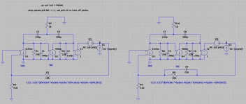
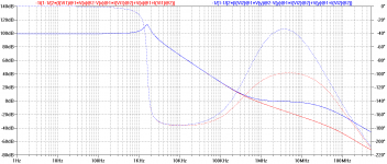
Refer to the attached simulation model of a TPC-compensated amplifier with the major loop gain given without phase lead compensation (red trace) and with phase lead compensation (blue trace).
Attachments
Last edited:
Modern output transistors, such as the MJL3281A/1302A, have ft in the region of 30MHz.
This suggests that their dominant poles are likely to reside at least a decade below this, at roughly 3MHz.
It's therefore wise to have your major loop ULGF below 3MHz for acceptable stability margins...
Yes, it is almost universal to keep well below the Ft of the outputs.
Certainly a safe way to to it.
But it is not clear to me why ULGF can't be raised considerably with appropriate cancellation of the output transistor pole.
A phase correction capacitor in the feedback loop can be used to do this, or used as you have done, to improve the stability but not alter the ULGF much. Or some trade-off of both.
It seems to be the most effective technique.
I have written this up for my next instalment in Linear Audio, if I may do a little advertorial
I know Bob Cordell worries about RFI susceptibility via this capacitor but I think that RFI can be dealt with separately.
Then this capacitor becomes a free parameter to optimise the return ratio.
I don't yet know what or where the limit is to increase the Unity Return Ratio Frequency.
Best wishes
David
Last edited:
...it is not clear to me why ULGF can't be raised considerably with appropriate cancellation of the output transistor pole...
The difficulty is that the location of the dominant output stage pole is unknown; unless you've figured out a method of establishing its location?

Is this not "two pole OIC (Output Inclusive Compensation"?
I'm finding relating (the equivalence of) this form of TPC to TMC a challenge.
Hi,
It is not OIC TPC. Now you can try OIC SPC (single pole/miller cap)
or indeed OIC TPC, (all compensation around the VAS and output),
but both are hopelessly unstable usually.
So TMC is a hybrid of TPC (on the VAS) and OIC TPC (on VAS and output).
The smaller cap applies feedback around the VAS only, like TPC, but
in TMC the other R and C apply feedback around the VAS and output,
like OIC TPC. Hence the transitional aspect to its naming.
rgds, sreten.
Last edited:
The difficulty is that the location of the dominant output stage pole is unknown; unless you've figured out a method of establishing its location?
Yes, I plan to actually do a measurement. What a concept
Best wishes
David
Hi,
It is not OIC TPC. Now you can try OIC SPC (single pole/miller cap)
or indeed OIC TPC, (all compensation around the VAS and output),
but both are hopelessly unstable usually.
rgds, sreten.
It is not always unstable, could be very stable, look here http://www.diyaudio.com/forums/solid-state/243481-200w-mosfet-cfa-amp-3.html#post3654509
Yes, I plan to actually do a measurement. What a concept
Best wishes
David
How?
Moreover, you'd have to perform the measurement for each ouput stage in your designs.
- Status
- This old topic is closed. If you want to reopen this topic, contact a moderator using the "Report Post" button.
- Home
- Amplifiers
- Solid State
- Demonstrating that TPC and so-called "TMC" are related