My Approach has always been using a seperate transformer from the amp which also contains the rest of the PSU...I.e. the power cables running into my GC's box is carrying stepped down AC.
Mains earth I terminate on the bolt on the transformer's case, from there I run a trhee-core wire with ends connected to the amp case from where its split with witha network of two 8A diodes, a 10R resistor and .1uF cap alll in series, nothing from the amp connects anywhere before this network... PS make the resistor a nice fire retardent one.... it burns to a crisp when something goes wrong on the amp in my experience...
mains---Transformer case ---- amp case ---- network---pgs/sgs/speaker returns...
The above describes the mains ground wire from where it is plugged into the wall onward.
I think what is missing from kvholio's diagram is secondary-side fuses. These would be what blows in the event of a sort to the chassis, rather then blowing up the bridge(s) and possibly melting the transformer secondaries, which may have a much lower current rating than the bridge. I think without these you risking electrocution, until the bridge burns up, when you risk fire.
If you use a seperate chassis for trafo/bridges, you shoudl have fusing at it's output as well as the input of the amp box.
If you use a seperate chassis for trafo/bridges, you shoudl have fusing at it's output as well as the input of the amp box.
Hi Kv,
I would keep to your compact philosophy.
i.e. keep the transformer and rectifier and first stage smoothing together.
Then run DC carrying cable to larger than normal decoupling to form second stage smoothing.
The short (low inductance) cable/track from decoupling to amplifier supports the high frequency demands.
The low frequency demand is still fed from the main smoothing capacitors.
Your grounding diagram needs a little refining.
Here is another option. I mention it, as no piece of consumer audio equiptment I have owned (until recently) has had a three prong plug (no earth safety ground).
In this picture, mains hot goes to fuse, then power switch, the torroid. Nuetral goes to torroid. Again, no ground.
The chassis is "grounded" to the torroid's center tap. Both secondary rails are fused.
In this picture, mains hot goes to fuse, then power switch, the torroid. Nuetral goes to torroid. Again, no ground.
The chassis is "grounded" to the torroid's center tap. Both secondary rails are fused.
An externally hosted image should be here but it was not working when we last tested it.
I'm not prepared to discuss the possibility of ac-mains powered equipment in a metal case
without a connection from the case to safety-earth.
I think it's inherently unsafe to do so.
We all know it's theoreticallly possible to construct it that way,
and we probably all have practical examples at home.
In my opinion it's not doable from a diy- point of view.
Also i don't see what there's to be gained from 'physically stretching' the psu by dividing it into 2 cases
(assuming a gainclone with only smoothing-caps on the amplifier-pcb).
Only in case of 2-stage smoothing (like AndrewT suggests) i can see some possible merit in putting the psu in a separate case.
So what are we building here ? i thought the thread-starter was going for a one-box solution.
Best regards,
Klaas
Your grounding diagram needs a little refining.
I would appreciate suggestions.
best regards,
Klaas
Hi Kv,
the link from upper cap to lower cap carries the impulsive charging current.
Similarly the link between the transformer secondaries (the centre tap).
The link from centre tap to capacitor 0V (zero volt or PSU common) carries no current when the amp is idling ( it carries a small current if the voltage amplifier uses different currents from the +ve and -ve rails). It carries current when the amplifier puts current into the load. This output current follows the signal and so is less impulsive than the charging pulses and for low output is very small. For large outputs it is very large but then a tiny bit of voltage difference is unlikely to be heard.
I suggest you connect centre tap to PSU common as shown but move the other two connections.
The disconnecting network, from the safety earth could be connected to the centre tap.
The speaker return and the decoupling returns could also be connected to the centre tap.
All the low current audio grounds should be brought together and then linked to the centre tap.
This is nearly the same as you have, the main differences are moving everything across to the centre tap and separately connecting the large current returns to the 0v ground. Some might say this is no significant difference and I have to admit I have not been able to measure any difference. However many amplifiers have multiple smoothing capacitors. With multiple caps there is no single 0V point whereas the centre tap is almost a single point.
Show the box of low current audio grounds as star connected rather than a string. In your diagram only the middle connection needs to be relocated up to the star point.
Delete the reference to a resistor in the note "offset between powersupply-ground and audio ground ( length of wire, bolt, or trace on pcb)"
I like the way you show the broken line box around the charging circuit. This could have a note added to say "keep the loop area of the two charging circuits as small as possible"
AndrewT, thank you for taking the time to write such an extensive reply.
If i understand correctly, you want to use the transformer's center-tap as ps-ground.
I see your reasoning behind it , but isn't there a practical issue to consider here also ?
A lot of times the transformer (and thus the center-tap) is located far away from the audio-circuit for practicality-reasons.
Using the center-tap as ps-gnd would in this case mean a longer ground-connection from the audio-gnd to ps-gnd, OR longer connections from the amplifier-circuitry to audio-gnd.
I think this longer connection/connections would be more sensitive to hum/noise pickup.
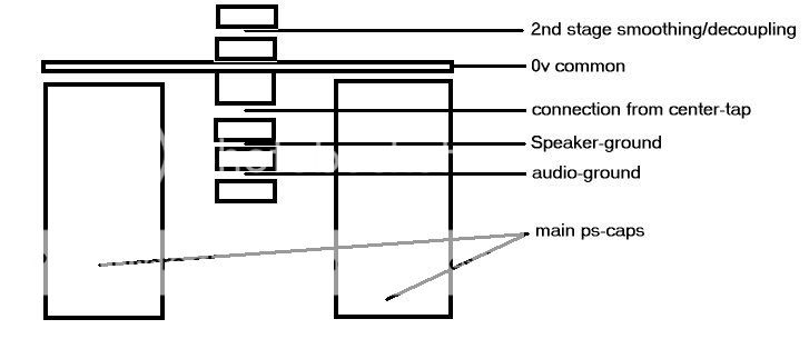
Using a bolt-configuration my suggestion would be as follows:
Connect center-tap at bolt FIRST
Then connect speaker-gnd at bolt
Then connect audio-gnd at bolt (or a piece of wire to create more offset from audio-gnd to ps-gnd)
Connect 2nd-stage smoothing/decoupling on opposite side of 0v-common
Like this:
Best regards,
Klaas
If i understand correctly, you want to use the transformer's center-tap as ps-ground.
I see your reasoning behind it , but isn't there a practical issue to consider here also ?
A lot of times the transformer (and thus the center-tap) is located far away from the audio-circuit for practicality-reasons.
Using the center-tap as ps-gnd would in this case mean a longer ground-connection from the audio-gnd to ps-gnd, OR longer connections from the amplifier-circuitry to audio-gnd.
I think this longer connection/connections would be more sensitive to hum/noise pickup.
Using a bolt-configuration my suggestion would be as follows:
Connect center-tap at bolt FIRST
Then connect speaker-gnd at bolt
Then connect audio-gnd at bolt (or a piece of wire to create more offset from audio-gnd to ps-gnd)
Connect 2nd-stage smoothing/decoupling on opposite side of 0v-common
Like this:
Best regards,
Klaas
Can someone please post the recommended resistor and cap values, capacities and types for the optimum mains ground decoupling circuit shown above? That was very interesting stuff. I'm an extreme newbie and I engaged AndrewT in a battle of wits on a related thread which I was not prepared to win 
Hi,
I would swap second stage smoothing with the centre tap.
The current from centre tap to PSU 0v is the connection likely to have the worst charging pulses and as a result the worst buzzing.
Keep that current away from the signal side of the bolted connections.
I would take the Thiel/Zobel return to the decoupling / speaker gap.
You have shown spacers. I think it will do no harm to remove most of them. I use none, just solder tags. Experimentation should be very easy since all is bolted.
The idea you have shown is very similar to what JE Sugden did on the elderly P128 but the decoupling and signal and RCA input all share a wire to a remote part of the PCB. There is a small residual hum and buzz. I intend separating the grounds at the PCB to try and improve this and show that an audio ground can successfully share the bolt with the PSU 0v if done properly. But I have a lot of cutting and patching to do on the PCB so this part of my research is still some weeks away.
Agreed.I would swap second stage smoothing with the centre tap.
To me the most important thing is, your transformer center-tap is your powersupply-ground.NOT your common connection between your smoothing-caps.
Klaas
Hi all
In my view, using insulated RCA phonos at the inputs, and insulated output and ground return sockets for the speaker power seems to work without needing an earth disconnector.
With this approach all the power return grounds and input grounds are brought (with separate wires, twisted pairs for the power etc) to a common earth point on the chassis. I usually make this the 0V from the power caps also, since although there is a high current noise from the caps, the resistance will be lowest at this point. Which makes the power ripple voltage as small as it can be.
Prof. Cherry used to recommend bringing the output ground return to the chassis and using chassis-connected phonos for the inputs. I have not found this to work when a preamp is connected which is also earthed. I have not tried disconnector schemes in that setup yet.
Anyone else tried Cherry's approach?
cheers
John
Hi John,
It would be nice to know how to make this work.
From what you have described, I think I have tried this and failed to eliminate all noise from the output.
I wonder if the reason my version failed is that the impedance of the mains supply earth is lower than the amplfier impedance. So then the spikey low impedance contaminates the higher amplifier impedance.
Your observation that a mis-wired source will cause hum is very valid. Two mis-wired units causes the hum loop.
That becomes the main downfall after you eliminate the buzzes.
Can you give more detail?In my view, using insulated RCA phonos at the inputs, and insulated output and ground return sockets for the speaker power seems to work without needing an earth disconnector.
It would be nice to know how to make this work.
From what you have described, I think I have tried this and failed to eliminate all noise from the output.
I wonder if the reason my version failed is that the impedance of the mains supply earth is lower than the amplfier impedance. So then the spikey low impedance contaminates the higher amplifier impedance.
Your observation that a mis-wired source will cause hum is very valid. Two mis-wired units causes the hum loop.
That becomes the main downfall after you eliminate the buzzes.
Hi,
I really liked his treatment of Thiel Network. And use it.
I would still like to try his nested feedback loops, but some others think his theory is flawed, leading to poor sound quality/oscillation on awkward loads.
I have read some of Dr Cherry's WW article's .john_ellis said:Prof. Cherry used to recommend bringing the output ground return to the chassis and using chassis-connected phonos for the inputs. I have not found this to work when a preamp is connected which is also earthed. I have not tried disconnector schemes in that setup yet.
Anyone else tried Cherry's approach?
I really liked his treatment of Thiel Network. And use it.
I would still like to try his nested feedback loops, but some others think his theory is flawed, leading to poor sound quality/oscillation on awkward loads.
- Status
- This old topic is closed. If you want to reopen this topic, contact a moderator using the "Report Post" button.
- Home
- Amplifiers
- Chip Amps
- Definitive earthing advice sought.