I recently came across a B&K CS-117 Preamp, it was part of a larger lot of stuff I dragged home and I was told it 'just quit working one day' but its former owner. Its spot clean inside an out.
I did Google search and saw that the transformer is a likely issue on these. I also searched for a manual or schematic but didn't see any.
With this thing plugged in, I'm seeing two voltages out of the transformer, both 24v and 13.5v The transformer has nothing on it saying what it is or what voltage it should be. Following the wires to the main boards, I can trace the power to the boards and can see power is getting to the switch.
The switch does nothing there's no light, no click, no relay noise, nothing. The fuse I found is good, and the switch tests out as far as continuity.
There's a few opp amps on the board but I have no idea what they do or if they could even be at fault but this seems like a power issue not a failed component.
After hearing it just stopped playing, I was expecting to see something more drastic or a dead transformer but from past experience, most transformers usually fail by either just not making power or by short circuit across the primaries.
This is producing voltage and I can follow power from the power supply area of the main board to various points, including the selector/power switch on the left side.
It does use an LC7818 chip on the output board which I see has been a failure point on some receivers but without a diagram, its hard to tell how its being used on this.
There are no indicator lights working on any of the switches, it does not pass audio in bypass mode.
It acts as if there is no power but I have voltage on the main board which tells me the transformer is not 'dead'. I'd at least expect some sort of function.
The lights on the switched do show continuity so their not burned out but they're seeing no power.
I'm certainly just a novice at these things but what I'm thinking is that if it won't bypass sound, the issue has to be in the switching of the IC on the output board? I would think that with the bypass switch depressed, it should function solely as a volume control and nothing else?
Does anyone have any experience with these?
In the past I have run across a failed LC7118 that failed on a 90's receiver where it was being used in the tape monitor circuit, and thus blocking sound from the outputs, but without a diagram I'm guessing, and then, if it is bad, what likely killed it?
Although I figured my next step is likely to pull both boards out and look closer to how the pcb is laid out but figured I'd ask here before I over think this thing.
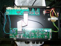

Here's what I have with the thing plugged in.
The transformer has three sets of taps.
120v in, and the three green outputs go to the main board,
as shown below as viewed from behind and above
There are also two more wires, a heavy red and heavy orange that come out of the lower windings which
go to a two pin terminal block that's not used, both of those wires read 148v ac, both higher than line voltage.
The transformer gets rather warm pretty quick but nothing on the board gets warm and it doesn't light the dbt.
No lights were lit when I had it on the bench the other day.
The tape monitor indicator is now glowing all the time, its a momentary button with no latch but otherwise the same button/swich as the bypass switch, must minus the flip flop lever or spring. Both boards are grounded with 12ga wire soldered to the chassis on each side.
If I unplug the power plug from the main board, I get 23.9v and 13.3v ac with the transformer not connected to anything but the voltmeter.
Wall power is reading 124v ac today, usually its a bit lower, closer to 117 or so here.
Here's what I have for volts on the two regulator transistors.
Re post 3 : so the voltage with unloaded transformer seems OK ? It should be about 15 + 15 volts or more.
Loaded down by the main board it is less ? This can destroy the transformer in the long term, hence the advice
to try an external supply. I do not completely agree with the suggestion that the "short" is "after the regulators"
(7815 and 7915) - you can check the four diodes near to the connector as next step, but probably the transformer
is already damaged. It is switched secondary only and so connected to the mains all the time.
Last edited:
The transformer appears to have an inverter leg for no reason?
The red and orange wires go to an unused terminal strip.
This is what I'm seeing at the transformer, unloaded:

The transformer still gets warm even when unloaded. its not too hot to touch but it gets warm fast.
I'm not sure what I can use to power the board directly or what voltages I should have where?
I can see the two regulators are rated at 15v, but this thing appears to have two voltages on the board at that plug.
Or is what I'm seeing the result of the damage?
I have no schematic for this.
What are the transformer voltages supposed to be on the secondary wires?
Nothing on the board gets hot, not even slightly, there's zero temp rise on any components using an infrared thermometer.
I would think if there were a short, I'd have something warming up fairly quickly?
I'm really not understanding why its got the 150V high voltage tap there? Its not used but why bother?
Could it be for a Euro version and the higher volts are something I'm reading as a by product of unused windings?
I also find it odd that the terminal strip, which has several unused spade connector points on it, is left out in the open like it is with no
insulation. If I follow the leads into the transformer, the yellow and white leads turn upward into the paper wrap, the red and orange go straight into the lower windings which are wider, but shorter than the rest.
Could the red and orange by an unused 240v input that's somehow giving me an inverted voltage on those wires? (Either way, its likely unrelated to what's going on here but I though it odd that I got such high readings off those wires).

The red and orange wires go to an unused terminal strip.
This is what I'm seeing at the transformer, unloaded:
The transformer still gets warm even when unloaded. its not too hot to touch but it gets warm fast.
I'm not sure what I can use to power the board directly or what voltages I should have where?
I can see the two regulators are rated at 15v, but this thing appears to have two voltages on the board at that plug.
Or is what I'm seeing the result of the damage?
I have no schematic for this.
What are the transformer voltages supposed to be on the secondary wires?
Nothing on the board gets hot, not even slightly, there's zero temp rise on any components using an infrared thermometer.
I would think if there were a short, I'd have something warming up fairly quickly?
I'm really not understanding why its got the 150V high voltage tap there? Its not used but why bother?
Could it be for a Euro version and the higher volts are something I'm reading as a by product of unused windings?
I also find it odd that the terminal strip, which has several unused spade connector points on it, is left out in the open like it is with no
insulation. If I follow the leads into the transformer, the yellow and white leads turn upward into the paper wrap, the red and orange go straight into the lower windings which are wider, but shorter than the rest.
Could the red and orange by an unused 240v input that's somehow giving me an inverted voltage on those wires? (Either way, its likely unrelated to what's going on here but I though it odd that I got such high readings off those wires).
I gave this some thought all night and got to thinking that the volts on the transformer didn't make sense, the loss was too great for any power supply, and the erratic light operation had me puzzled a bit.
I noticed that if I unplug the main board power connector the Tape Monitor light would flicker and go dim, but never go out, regardless of whether or not I was holding the button in or not. (I still don't get the momentary function of the tape monitor button, which is using the same model switch as the others, but with the flip/flop lever and slot not present).
The transformer was getting warm enough that I could smell it but it wasn't too hot to touch, but hotter than I'd expect something that size to get.
With it powered up, I started to unplug the cables to the rear board and found that when I unplug the ribbon cable the volts jumped up to 30 and 15V AC at the plug and the heat dropped on the transformer. Removing the wire plug near the phono jacks made no changes.
After the transformer cooled down completely, the standing volts remained the same, no loss due to load.
I pulled the rear board to have a closer look and found a good many of the traces wrinkled up, and three pins darkened on the LC7818, those correspond to pins B, C, & D on the ribbon cable.
That end of the chip is warmer than the rest of the chip.
I'm thinking that something took out LC7818 by overload and it failed? Its only slightly hotter than the rest of the chips when powered up but I believe it would prevent the thing from switching to bypass mode too.
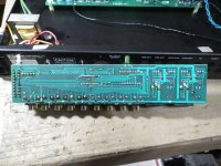
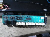
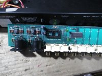
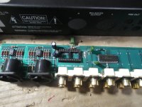


Well, did you notice this before and did not tell us ? You can read about defective B&K CS 117
transformers in other threads and that it may be caused by dead IC LC7818 on the rear board.
Disregard "wrinkled" traces on the board, this is caused by excessive solder in solder bath.
transformers in other threads and that it may be caused by dead IC LC7818 on the rear board.
Disregard "wrinkled" traces on the board, this is caused by excessive solder in solder bath.
Every time I plugged this thing it gave me different symptoms, the flickering tape monitor light and warm transformer sent me looking for a short. The more I thought about the voltages being so low the more the idea of a short sunk in I guess.
Is the LC7818 the most likely issue?
I've replaced one of those before but in a newer receiver that died after a power surge, but on that it was just dead, the unit lit up normally but had no sound output.
I may have one here somewhere, I'll have to do some digging, I could have sworn when I bought the one a few years ago I had to buy 5 of them. Of course it may be just as easy to order one.
I don't have any info on these, a web search turned up a few posts about someone searching for a transformer but my transformer wasn't dead. The first few times I tried this there were no lights working anywhere, and no noises or sound either. I pulled the cover and poked around a bit looking for something burnt or hot but didn't find anything. Now, after the fifth or sixth try, I noticed the lights flicker and the heat at the transformer. The bad part about this thing is that the transformer is hot all the time, that main board and power supply are always powered up, so the issue remains there all the time I suppose? If I get this thing working I think it'll be set up on a switch so it can be shut down when not in use. I don't like the idea of having that transformer hot all the time.
I'm not sure what their thinking was in not having the power switch kill the power supply? It seems like a bit of a fire hazard to me.
I'm seriously also considering adding a regular power switch to this before the transformer.
I finally found something on the transformer, its supposedly a 30v (15-0-15) .65a unit with dual inputs for both 120v and 240v.
I'm now not certain that the unused 240v taps should be inverting voltage like they are?
I can't say I've ever dealt with a dual input transformer like this, and certainly not one that had voltage output on the unused windings like this? Its apparently not affecting the output though and I'd pretty much have to figure that the 14.99v I'm seeing at the green wires is in spec. I would likely swap it out though if I had one or could find a suitable replacement without spending more than this thing is worth, but I think swapping out the LC7808 is likely going to be the fix, unless there's other damage along the way.
What I can't figure out is why when I pulled the power connector off the main board before I got lower voltage unless it was being affected by its being overheated.
I have some 30v transformers but their 3a and will not fit under the cover. I'll worry about that though after I figure out which box or cabinet the LC7808's are in first.
I think this is a more appropriate schematic for the transformer?
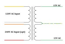

It kind of looks that way, all I have to do now is remember where I put the extra IC's I bought before.
I know I've got them around here somewhere.
What do you think about putting a power switch on this that kills the power to the transformer?
I really don't like the thought of this thing sitting there with power going through the transformer and power supply all the time.
I'm thinking of just putting a simple power switch on the front panel so I know its shut down when not in use.
I removed the LC7818 and powered it up without it and the short is not there.
I dug through as many boxes and drawers as I could but couldn't find the LC7818 chips I know I've got somewhere, so I ordered some more.
Do you think it will hurt this any to install a socket to hold the new LC7818? Those I did find.
My thought is that these things seem to be failure prone after reading about so many being bad.
I'm also still knocking around the idea of putting a power switch on this thing to kill power to the transformer when its not in use.
I could just power it off a power strip and master switch but its a lot cleaner to just have a switch on it to shut it down with.
I could put it on the front, on the right side, or on the rear panel next to the power cord.
I think this thing was worked on before, those three pins on the LC7818 that looked darker in the pics above were re-soldered at some point. They were coated in dried up flux. When I took the chip out, those three pins and the printed circuit traces around them were corroded, as were those three pins. The pin holes in the board are actually made larger with the ferrules gone that went through the board to the little pads on top. It shouldn't be an issue though as the top traces don't connect to the pins there.
I honestly think this thing would have been better off without that chip there to handle the switching functions, but the circuit to take its place would take some doing to build, so it gets a new chip for now, and likely a socket to make any future replacements easier. It'll also make cleaning up the board a bit easier without the risk of future damage removing the chip if another were to fail.
Last edited:
As far as I can tell the transformer is fine, I'm getting 15-0-15v on the outputs in AC volts, and there's 19.2 V ac after the four diode rectifier and over to the two regulators, and I figured that a few points over 15v is likely well within their spec.
Other than checking voltage, I'm not sure what else I can do to check the transformer.
The LC7818 is just a switching or selector chip, so it shouldn't be drawing down anything.
Being its a preamp, there's not a lot going on in there, which is likely why its got such a tiny transformer.
Other than checking voltage, I'm not sure what else I can do to check the transformer.
The LC7818 is just a switching or selector chip, so it shouldn't be drawing down anything.
Being its a preamp, there's not a lot going on in there, which is likely why its got such a tiny transformer.
- Home
- Source & Line
- Analog Line Level
- Dead B&K CS-117 Preamp