What happens if you inject a distorted signal => you will get distortion. A good example is if you use a LM324/358 which has extremely high crossover distortion.pjacobi said:I don't really understand, how a small DC component can significantly worsen an amplifier.
The reason for the DC offset is caused by the input stage of the amp, the main amp.hjelm said:Didn't quite get that.
What is the source of the DC component. Is it the signal source or do you say that a 1k signal has a DC component?
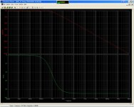
Maximum constribution from DC servo do you have at less than 1 Hz or so but above 1 Hz you will have a small portion of the audio which is put through this way. At 1 kHz this signal has dropped about 60 dB and it's becoming near the noise floor.
Conclusion: The opamp for a DC-servo must be good no doubt about it.
Hi Per-Anders,
I rather meant it the other way around: That the circuit would be better left without a servo and with a small DC offset.
Regards,
Peter Jacobi
peranders said:
What happens if you inject a distorted signal => you will get distortion. A good example is if you use a LM324/358 which has extremly high crossover distortion.
I rather meant it the other way around: That the circuit would be better left without a servo and with a small DC offset.
Regards,
Peter Jacobi
Maybe so but in my RIAA amp case with DC gain of 80 dB the offset would be 100 uV times 10000 = 1 V or even more.pjacobi said:I rather meant it the other way around: That the circuit would be better left without a servo and with a small DC offset.
You use DC-servo if:
The gain is high
The offset is high
The offset is drifting too much
You don't like big electrolytics, especially in low noise applications
A big cap takes up too much space
Werner:
The "Hawk", wasn't it? I've never heard one, but agree that adding the current-mirror output stage is a good approach for a servo that needs to interface with a complementary topology circuit.
Conversely, when the servo needs to interface with a differential topology circuit, you can add a differential output stage to the servo.
Either of the above approaches is a useful alternative to the single-ended methods discussed in the OP42 and LT1115 data sheets.
Stuart - I've also used passive poles at the servo output. I have mixed feelings about them, probably due to the fact that they should be tuned a good deal higher than the servo itself, and due to the higher tuning, can exert phase-shift on the lower octave in the audible range. But I have used this technique mainly for DC servos applied to the NFB loop of the signal amplifier - I don't have much experience with output passive poles combined with steering-current style servos. And of course, there could have been issues with how I implemented the passive poles.
regards, jonathan carr
Well, where I've used them, I haven't seen any sort of phase shift effect (other than from the principal servo time constant), but my experience in using this scheme with bipolar input stages is limited- like maybe twice. With FETs or tubes where I've been using these schemes for dozens of amps/preamps, the grid/gate resistor is so big that it really swamps out any effect from the varying source impedance of the servo due to that passive filter.
Most amps are DC servoed, by the amp feedback loop itself. Even if there is not a separate servo only circuit, the feedback loop is basically set up for gain of 1 at DC, since the divider to ground is blocked by the usual DC blocking cap.
Because this cap is often a non-ideal part for the job (should be bipolar, and fairly high value and low leakage), people like the idea of removing it, connecting to ground, and using a separate OP amp to null any offset. But sometimes these circuits are not designed well and the servo has turn on bumps, or other artifacts that cause more problems than they cure. Perhaps that is the reason they are frowned on by some. Others compare the cost of a bipolar cap to the cost of the OP amp and associated components and say why bother? Both approaches can work well if properly implemented.
One thing I do recommend if you use the cap, bypass it in both directions with a couple of signal diodes (1N4148 or such). The reason is if one leg of the output stage fails, you need a DC path to ground for the high voltage that will come in on the feedback line. I've seen caps exploded and the entire input stage blasted. If you have to fix these, you wish someone had thought about the failure mode and put in a few cheap diodes. Just my personal opinion after fixing quite a number of these and having to replace all the input pairs....
SY said:Interesting. That's the first time I've seen a commercial amp use the trick that I use in my servo circuits- a passive pole in the output. Normally, I set it about a decade above the integrator time constant- do you know the values of R21/C8 and C6/R19?
I use passive filter on the output of my DC servos too. I set the filter about 2Hz, to cancel all the noises sent by the opamp.
Another trick I use, the resistor conneted from the output of the opamp to the negative rail. The resitor is about 3.3k for +/-15V, set 5mA bias for the opamp output, and set it into class A, and ignore all the crossover distortion.
Sajti
There was once an Elektor circuit that used two additional poles within the servo circuit.
IMO they shouldn't add any phase-shift to the audio signal but they should reduce negative effects of the loop like THD from the OP-AMP.
IMO any circuit with a servo should have an input cap as well which determines the lower cutoff frequency of the circuit. The time constant of the servo should give an additional highpass-pole that is at least an order of magnitude lower than the one given by the input cap/resistor. So it wouldn't do too much damage to the signal itself. The additional poles of the servo should again be significantly higher than the pole given by the integrator (as mentioned by SY) to maintain stability.
Anyone ever thought of a servo with two selectable time-constants in order to achieve a shorter turn-on settling time ?
Regards
Charles
As I found, settling time is not a big problem, if the output of the servo is close to the 0V, during the operation. This means almost 0 voltage over the output filter cap, and there will be no audible effects.
The passive output filter reduce the turn on anomaly too.
I found some ringing only when the time contant are same. but with two poles, there was no oscillation.
Sajti
The passive output filter reduce the turn on anomaly too.
I found some ringing only when the time contant are same. but with two poles, there was no oscillation.
Sajti
phase_accurate said:
Anyone ever thought of a servo with two selectable time-constants in order to achieve a shorter turn-on settling time ?
The Audiolab / TAG-McLaren phonostage.
Attachments
Bad Servos?
Servos are normally badly implemented due to the -3dB point being far to near the audio band. The -3dB point should not be at 1Hz as a lot of audio is still being fed back into the amp at higher frequencies as can be shown on the graph with a -3dB point of 1Hz. It should be around a -110dB point at around 10Hz for the servo to have no effect on the audio signal but this causes another set of problems which take extra circuitry to solve. I would not feed any signal which is not from the source or is direct feedback from the amps output into one of the differential amplifiers inputs, certainly not a -60dB signal at 1kHz as shown on the graph. This is bound to cause serious alterations of the original signal.
Each line on the Y scale is 20dB.
Regards
David
Attachments
Servos get a bad rap. I don't claim that they ever can be 'perfect' but usually they are designed to respond too quickly in order to give a fast turn-on, and then tend to respond to the asymmetry in any audio waveform coming from the source. We can be pretty sure that DC is NOT part of the actual audio signal, but asymmetric waveforms are common. This creates a DC like component that can effect servos big time. The audio signal cannot maintain this DC component for long, but if the servos are quick to respond, then they will start to significantly put out a 'correction signal' that will change the waveform. This is not good.
It would be better to use a coupling cap to roll off this DC component if it was necessary to do so.
It would be better to use a coupling cap to roll off this DC component if it was necessary to do so.
Re: Bad Servos?
If you choose a LM324 you have problems but if you choose a AD8610 it's not wrong to choose a frequency which not interfere with max power at the 20 Hz or so. Meaning the servo should not clip at max power.NET Audio said:Servos are normally badly implemented due to the -3dB point being far to near the audio band.
John, I see no problem with ANY output signal as long as the servo acts in it's linear mode and not clips. The servo acts like a artificial capacitor.john curl said:Servos get a bad rap. I don't claim that they ever can be 'perfect' but usually they are designed to respond too quickly in order to give a fast turn-on, and then tend to respond to the asymmetry in any audio waveform coming from the source. We can be pretty sure that DC is NOT part of the actual audio signal, but asymmetric waveforms are common. This creates a DC like component that can effect servos big time.
I have simulated my Gainclone DC servo in order to trim the values and I see not way to turn-on the servo faster than a simple intergrator. You can add deriving functions but then it isn't a DC servo.
John, DC doesn't exist. DC is extremely low frequency and the servo is removing the AC component from 1-10 Hz (of both the audio but also disturbance) down to 0.00000000000001 Hz.
- Status
- This old topic is closed. If you want to reopen this topic, contact a moderator using the "Report Post" button.
- Home
- Amplifiers
- Solid State
- DC Servos - Why Are They Badly Regarded ?