Klaus,
"Life is too short!" is something that I often try to keep in mind.")
Yes, I, too, think it would be interesting to be able to simulate with more-realistic models, especially for capacitors.
For transient sims, I do often use at least a simple linear model for ESR vs frequency, with a param statement or two for each capacitor type and value. That is a little (or a lot) tougher to do, for AC Analysis, since spice won't re-evaluate .PARAM statements at each frequency. But it can be done, using a LaPlace source to make a frequency-dependent resistor. There can be fairly-large ESR variation versus frequency, even just over the audio range, for electrolytic capacitors at least.
There are many more-intricate capacitor spice models, and discussions of same, in the Files area and message archive of the LT-SPICE discussion group, at http://www.yahoogroups.com . The problem, for me, is coming up with the parameters and data for the models! It would be time-consuming to measure evferything, for each type and size of capacitor, even if I had all of the necessary and sufficient equipment and knew how to do it. And it seems to be very difficult to find the necessary data, elsewhere, at least for me. (Except that Kemet has lots of data and software for better-than-usual spice models of their capacitors. But, unfortunately, they apparently don't have any standard electrolytic types.)
I keep telling different component manufacturers that if they would provide good spice model libraries for all of their components, then they would _sell_ more components. A great example, besides the semiconductor companies, who are mostly already fairly good, is the Epcos thermistor spice model library. It's great. Their models also include self-heating effects, too. Without that library, I would really hate to have to design almost anything with thermistors. But WITH the library, I can even "measure", with spice, a thermistor's resistance at three temperatures, and then use the thermistor linearization formula to calculate the resistor value required to linearize the thermistor in any temperature range, and then immediately plot the "actual" resistance vs temp curve. And if a NON-linear curve is required, it's at least bearable, with spice, to check the results and maybe iterate a little, to get the curve "just right".
Anyway, I wish that there were better models already available, and also that spice had better built-in facilites for accomodating more-detailed effects in passive components' models. And, of course, I wish that I was "up to speed" on the better modeling and simulation techniques that are already available. If you have or find any good modeling and/or simulation techniques, I'm sure that many people would be very interested in knowing about them.
Actually, what I REALLY wish is that the "spice professionals" would come up with everything we need, and just provide it all, so that we could just be "users", and less like developers. I often hardly have time to be both.
Thanks again, Klaus.
- Tom Gootee
http://www.fullnet.com/~tomg/index.html
"Life is too short!" is something that I often try to keep in mind.
Yes, I, too, think it would be interesting to be able to simulate with more-realistic models, especially for capacitors.
For transient sims, I do often use at least a simple linear model for ESR vs frequency, with a param statement or two for each capacitor type and value. That is a little (or a lot) tougher to do, for AC Analysis, since spice won't re-evaluate .PARAM statements at each frequency. But it can be done, using a LaPlace source to make a frequency-dependent resistor. There can be fairly-large ESR variation versus frequency, even just over the audio range, for electrolytic capacitors at least.
There are many more-intricate capacitor spice models, and discussions of same, in the Files area and message archive of the LT-SPICE discussion group, at http://www.yahoogroups.com . The problem, for me, is coming up with the parameters and data for the models! It would be time-consuming to measure evferything, for each type and size of capacitor, even if I had all of the necessary and sufficient equipment and knew how to do it. And it seems to be very difficult to find the necessary data, elsewhere, at least for me. (Except that Kemet has lots of data and software for better-than-usual spice models of their capacitors. But, unfortunately, they apparently don't have any standard electrolytic types.)
I keep telling different component manufacturers that if they would provide good spice model libraries for all of their components, then they would _sell_ more components. A great example, besides the semiconductor companies, who are mostly already fairly good, is the Epcos thermistor spice model library. It's great. Their models also include self-heating effects, too. Without that library, I would really hate to have to design almost anything with thermistors. But WITH the library, I can even "measure", with spice, a thermistor's resistance at three temperatures, and then use the thermistor linearization formula to calculate the resistor value required to linearize the thermistor in any temperature range, and then immediately plot the "actual" resistance vs temp curve. And if a NON-linear curve is required, it's at least bearable, with spice, to check the results and maybe iterate a little, to get the curve "just right".
Anyway, I wish that there were better models already available, and also that spice had better built-in facilites for accomodating more-detailed effects in passive components' models. And, of course, I wish that I was "up to speed" on the better modeling and simulation techniques that are already available. If you have or find any good modeling and/or simulation techniques, I'm sure that many people would be very interested in knowing about them.
Actually, what I REALLY wish is that the "spice professionals" would come up with everything we need, and just provide it all, so that we could just be "users", and less like developers. I often hardly have time to be both.
Thanks again, Klaus.
- Tom Gootee
http://www.fullnet.com/~tomg/index.html
KSTR said:Hi Tom,
I'm about to think this all over again, right from the beginning...
I can see no other reason for the AC feedthrough to be as low as possible than to assume significant distortion in the servo, be it the op-amp itself or its associated components (cap parasitics, mainly).
As far as I see it (would need to do the math in detail, of course), with a plain 1st-order servo we have exactly the same transfer function of the signal amp as an input RC-coupling would have, plus we can cancel output offsets. For noise and feedthrough optimization, a post filter (simple RC) seems to be a good choice. I doubt a reasonable amount of overshoot from the additional phase lag will do any harm, but we could split the poles significantly if we lower the effective servo time constant (not just its R*C) and rise the post filter corner if that is an issue. Still we would have the additional -20dB/dec roll-off in the audio band. As an effective -3dB point fot the signal gain, from the servo action, I think around 0.1Hz might be a good compromise, regarding signal phase, response time and feedthrough attenuation.
Regarding catch range, I'd say, besides the consideration of worst-case DC values for input and output offsets, one should check that a, say, 5Hz or 10Hz full-scale signal will not saturate the servo, just to be on the safe side concerning deliberate input signals. I forgot to look at that in my circuit. Full-scale (6Vp input, x3 gain, 20V supplies) signals below 20Hz would clip the servo right away... lowering the corner to 0.1Hz (130k, 220nF) would meet a 5Hz target (5.6Hz, actually), having 2V headroom on the supplies and a DC offset catch range of a little more than 100mV/300mV. Also, input common mode voltage is a issue with a non-inverting servo circuit, which would swing almost +-13V @ 5Hz in my case. And here Andrew made a good point: if we ever encounter phase reversal from the servo op-amp we are in serious trouble. From the viewpoint of headroom issues a lower servo R*C is a good thing. To get the same signal corner freq and step response, we could decrease the injection R accordingly, increasing DC catch range as well (at the cost of increades noise, maybe)
Concluding, I'd say I would rather have some AC if we can get it clean and distortion-free than trying to reduce it with a lot of components that might add their own coloration. This leads to a solution like this (if we assume to be in the cost-is-not-an-issue camp):
- 1st-order servo, inverting, using an OPA627-quality chip, bulk metal R and teflon foil C. Inverting mode is beneficial for distortion and CM issues (the latter easily to clamp). Maybe a clamp of the intergrator itself is also a good thing to have, though it seriously complicates matters
- post filter, again bulk metal and teflon.
- execellent supply/bypassing and layout. It's clear that the servo needs as much attention to this as the signal amp.
- depending on the main amp config (I'd prefer inverting there, too) injection of the servo signal in the proper way, and if we have offset pins available on the main amp one could use these also. In any case we'd need a buffer / low impedance source for inverting servo config because we have to inject at the +IN of the main amp unless we can use its offset pins and run it non-inverting.
- Klaus
Thanks Klaus.
After reading this, I too decided to try re-thinking the whole servo design thing.
I haven't had much time to do anything on it, yet. But, back then, I did start by creating simulations of the simplest-possible 1st-order (i.e. integrator only with no filters) servo loops, with the power amp LT-Spice test-setup, of the last schematic that I posted.
In both cases (i.e. inverting amp and integrator, and non-inverting for both), I did see extremely-low reported THD, even in the presence of large AC feedthrough from the servo loop, which surprised me, and also tends to verify the view that you stated earlier, about that.
But I still also wonder how true that might be for the real circuits, and what the simulation might be treating as ideal that might make it not so true, in a real circuit. [Aside: I've got everything I need to breadboard the circuits, and even fairly-quickly put them on pcbs if necessary, plus lots of test equipment (from back when I used to refurbish and resell it), including some great Tektronix scopes, some decent signal generators, etc, plus an HP 334A distortion analyzer, and even some phase-angle voltmeters, plus some great older HP power supplies, and maybe even a soon-to-be-working Genrad audio spectrum analyzer, and, a whole lot of other stuff. So "someday soon", maybe I'll try to get a dedicated testbed in place, so I can try to check simulation results as I run them. I do hate the feeling of "not really knowing" how much to trust the Spice results.]
I also found, again, that it is much more work to design a servo loop with a non-inverting integrator, for a non-inverting amplifier, that it is to design a servo loop with an inverting integrator, for an inverting amplifier. The integrator-only topology might even be the worst-case scenario, for that, regarding the most-basic issues, anyway. And with no pre-filter for the non-inverting integrator, a resistive divider between the main amp's output and the integrator's input is probably unavoidable, but creates still more design issues. It's definitely not as easy as I thought it would be. (Of course, it may not even be a "practical" topology. But I wanted to be able to compare the inverting and non-inverting cases, in their simplest forms, to start with.)
The gain of the main amplifier can also be significantly affected, in the non-inverting case. Luckily, in that case, unlike the inverting case, the gain and phase angle of the feedback's AC level both stay flat through the audio band, if the servo loop's R and C values are chosen correctly.
More later, hopefully. I just wanted to mention that I, too, felt the need to re-evaluate the theory of DC Servo circuits. Unfortunately, for me, I think that, in my case, that will involve a lot of re-learning. (And I STILL haven't found my EE382 book, "Feedback Control Systems". But I did find my EE602 book, "Modern Control Theory". It quickly brought to mind the title of the Neil Young song, "Rust Never Sleeps".
- Tom Gootee
http://www.fullnet.com/~tomg/index.html
KSTR said:Hi Glen,
I look forward to see your cancellation circuit if you are willing to share. AFAIK you're in the low-level sensoring business so no doubt you have something serious.
My scepticism on cancelling methods for audio is the dirty nature of the residual one might end up with. Here of course we are already subtracting small quantities from each other so it probably wont matter much.
- Klaus
Hi Klaus,
I did play around with the AC-cancellation circuit, as described by Glen, but only in LT-Spice, so far.
I first used a "literal" interpetation of his description of the process, and implemented a signal path with a buffer, an AC-coupling capacitor, and a unity-gain inverter, to get "inverted AC only". That was then sent to a non-inverting summing amplifier, along with the original signal, where it was supposed to cancel the non-inverted AC component.
But later I looked at it again and realized that the topology could be reduced: The inverting amp and summing amp together were equivalent to just using a differential amplifier (unless there is some other advantage to the first implementation, that I am missing).
So, my latest implementation has: an optional RF filter (1k/1000pF lowpass), and then the signal splits and goes to two unity-gain opamp buffers. Those buffers' outputs both go to the two inputs of a differential amplifier, except that after one buffer's output, there is an AC coupling capacitor (the one that goes to the differential amp's negative input's resistor).
That topology is quite reminiscent of a simple instrumentation amplifier.
I also found that that circuit's high-frequency performance (i.e. 1 kHz and above) is extremely sensitive to any capacitance in the feedback resistor for the differential amplifier.
With a high-speed opamp type, and a nominal 0.3 pF of parasitic capacitance for the diff amp's feedback restistance, and using 2.2 uF for ac coupling and 100k for the four diff amp resistors, the circuit gives 20 dB/decade lowpass behavior, with a cutoff around 1 Hz. Then there is a fairly-deep notch at around 2 kHz, where the response is about 100 dB down. After that, the response rises again, in symmetrical fashion, until it starts to level off at about 100 kHz, at about 30 dB down. Then, depending on opamp speed, it may or may not peak and will start to roll off again, somewhere between 1 MHz and 6 MHz. (WITHOUT the RF Filter, it rises symmetrically all the way out to 1 to 10 MHz (depending on opamp type), and gets back up to the same level as at low frequency, before it rolls off again.)
BUT, WITHOUT the 0.3pF across the diff amp's feedback resistor (and with or without the RF Filter), there is no notch at low kHz and no symmetric rise. It just rolls off until about 100 kHz, where it levels-off at around -105 dB, has a peak somewhere before 10 Mhz (depending on opamp speed etc), and then continues to roll off.
It looks like the best bet might be to "swamp out" the parasitic capacitance of the feedback R, and then balance it on the other input: By putting 10 pF across the (100K) feedback resistor for the differential amplifier, and then ALSO putting 10 pF from the diff amp's positive input to ground, the response goes monotonically downward out through 100 MHz. And by changing those both to 100 pF (depends on opamp type), the response keeps almost a straight-line downward slope until around 500 kHz (depending on opamp type; try LT1364 with 100 pF, and then LT1115, to see differences), then levels off in the -120 dB region (-140 dB for LT1115), and rolls off again somewhere between 10 Mhz and 100 MHz.
Below is one implementation of the final topology discussed above, for the cancellation circuit.
An externally hosted image should be here but it was not working when we last tested it.
Note that in some cases (or maybe in many cases?), the two unity-gain buffers could be omitted.
The values for capacitors C4 and C5 will probably need to be tweaked, based on the type of opamp used, and the values of the other components that are used. The phase response can be made pretty flat at 90 deg, through the audio band.
I forgot to mention capacitor C2: Without it, the DC output level is only half of what it should be.
Tom Gootee
http://www.fullnet.com/~tomg/index.html
Hi Tom,
You keep stirring that pot and make others think, that's great.
To take part in this competition , I came up with a servo circuit -- see attachment --, inverting type (both signal and servo), that can achieve an overall -80dB/dec. slope for the feedthrough in the audio range, and which is more than 100dB down from the signal at 20Hz. And yes, it uses that "AC-cancellation" but in a IMHO simpler and less critical hook-up, using only one op-amp and passive summing.
The trick is to use a 180 degree phase shifter after the integrator, for DC and below its corner it's non-inverting with gain=1, above inverting with gain -1. This signal is summed passively with the integrator output, giving a gain of 1 for DC and "close to zero" for AC. "Close to zero" is the typical -20db/dec slope of the RC-lowpass (your design shows this, too). The advantage is the higher impedances that can be used with it and that there are no matching issues. Response-wise, there is no difference between an RC-lowpass and any "cancelling" circuit -- with the exception that one can trim the cancelling circuit to give a notch somewhere while a simple RC does not give any notch (but also flattening out and rise when the cap's ESR and ESL come into play).
The summing action (that is, actual an arithmetic mean value generation) is combined with a post-filter and the voltage divider (which goes to the +IN of the signal amp). The post filter is doubled in each leg of the summing network. I could arrive to very reasonable part values for the use of FET-input op-amps (OPA134) in the servo and a BJT main amp (LM4562, like the OPA134 coarsly modelled as perfect single pole, to concentrate on the principles of the circuit). Impedance matching is included. Still it's a lot of parts (like 5x 2.2uF of good quality) and some resistor matching/trimming seems necessary. To get the 4th-order roll-off, I also included a pre-filter. I tried some component value deviation/mismatch, the effects are rather benign.
The time constants were chosen as follows, with priority on usefull part values: I wanted the effective integrator pole at around 0.1Hz. This requires the local intergrator pole to be higher, the factor being the closed loop gain that the servo sees. For a resonable catch range I set the injection divider at 1:10, inverting signal gain is close to 3, giving a gain of 0.4, thus a factor of 1/0.4=2.5 for the local pole frequency which becomes 0.25Hz. The pre-filter pole was set to x4 of that, 1Hz. And both phase-shifter and post-filter poles were set to 3Hz to not add to much phase shift. The pre-filter adds 7 deg to the phase, and the 3Hz poles add 2 deg each, giving a total 80 deg phase margin which is more than safe at any rate.
Settling time to a step input is on the order of ten seconds with zero overshoot, catch range is about 2V input referred, signal roll-off breaks in at 0.1Hz, there is little overshoot in the freq. response (only 0.5dB at 0.4Hz) and the AC-feedthrough is extremely low, expressed in terms of the output voltage:
-20dB @ 0.7Hz
-40dB @ 2.3Hz
-60dB @ 5Hz
-80dB @ 9Hz
-100dB @ 15Hz
-120dB @ 30Hz
...
Attenuation flats out to a constant -230dB from 1kHz to 500kHz, the rising again with 6th-order roll-off. Of couse that's only "perfect sim" values no way to be reached in a real circuit, but I feel a 50Hz...20kHz attenuation at somewhere in the -120dB (1ppm) ranges is doable, with care. The post-filter and divider are the key points for low noise/distortion/feedhtrough contribution from the servo circuitry.
Ah, like you I got quite some notching and peaking in the response plot of the servo loop, especially when simulating stray capacitance and component parasitics...
Now that whole thing with non-inverting signal amp is to be thought about... I thing one can keep the inverting integrator and invert the signal in the filtering/cancelling stage that follows it...
Regards, Klaus
You keep stirring that pot and make others think, that's great.
To take part in this competition
, I came up with a servo circuit -- see attachment --, inverting type (both signal and servo), that can achieve an overall -80dB/dec. slope for the feedthrough in the audio range, and which is more than 100dB down from the signal at 20Hz. And yes, it uses that "AC-cancellation" but in a IMHO simpler and less critical hook-up, using only one op-amp and passive summing.The trick is to use a 180 degree phase shifter after the integrator, for DC and below its corner it's non-inverting with gain=1, above inverting with gain -1. This signal is summed passively with the integrator output, giving a gain of 1 for DC and "close to zero" for AC. "Close to zero" is the typical -20db/dec slope of the RC-lowpass (your design shows this, too). The advantage is the higher impedances that can be used with it and that there are no matching issues. Response-wise, there is no difference between an RC-lowpass and any "cancelling" circuit -- with the exception that one can trim the cancelling circuit to give a notch somewhere while a simple RC does not give any notch (but also flattening out and rise when the cap's ESR and ESL come into play).
The summing action (that is, actual an arithmetic mean value generation) is combined with a post-filter and the voltage divider (which goes to the +IN of the signal amp). The post filter is doubled in each leg of the summing network. I could arrive to very reasonable part values for the use of FET-input op-amps (OPA134) in the servo and a BJT main amp (LM4562, like the OPA134 coarsly modelled as perfect single pole, to concentrate on the principles of the circuit). Impedance matching is included. Still it's a lot of parts (like 5x 2.2uF of good quality) and some resistor matching/trimming seems necessary. To get the 4th-order roll-off, I also included a pre-filter. I tried some component value deviation/mismatch, the effects are rather benign.
The time constants were chosen as follows, with priority on usefull part values: I wanted the effective integrator pole at around 0.1Hz. This requires the local intergrator pole to be higher, the factor being the closed loop gain that the servo sees. For a resonable catch range I set the injection divider at 1:10, inverting signal gain is close to 3, giving a gain of 0.4, thus a factor of 1/0.4=2.5 for the local pole frequency which becomes 0.25Hz. The pre-filter pole was set to x4 of that, 1Hz. And both phase-shifter and post-filter poles were set to 3Hz to not add to much phase shift. The pre-filter adds 7 deg to the phase, and the 3Hz poles add 2 deg each, giving a total 80 deg phase margin which is more than safe at any rate.
Settling time to a step input is on the order of ten seconds with zero overshoot, catch range is about 2V input referred, signal roll-off breaks in at 0.1Hz, there is little overshoot in the freq. response (only 0.5dB at 0.4Hz) and the AC-feedthrough is extremely low, expressed in terms of the output voltage:
-20dB @ 0.7Hz
-40dB @ 2.3Hz
-60dB @ 5Hz
-80dB @ 9Hz
-100dB @ 15Hz
-120dB @ 30Hz
...
Attenuation flats out to a constant -230dB from 1kHz to 500kHz, the rising again with 6th-order roll-off. Of couse that's only "perfect sim" values no way to be reached in a real circuit, but I feel a 50Hz...20kHz attenuation at somewhere in the -120dB (1ppm) ranges is doable, with care. The post-filter and divider are the key points for low noise/distortion/feedhtrough contribution from the servo circuitry.
Ah, like you I got quite some notching and peaking in the response plot of the servo loop, especially when simulating stray capacitance and component parasitics...
Now that whole thing with non-inverting signal amp is to be thought about... I thing one can keep the inverting integrator and invert the signal in the filtering/cancelling stage that follows it...
Regards, Klaus
Attachments
There is another issue with servos which is not covered enough yet. I'm talking about the psu for the servo. One should strieve for maximal isolation, so you could always build a second one for the servo only.
If we don't want to do this, what else can we do? We'd need an low drop, high isolation and low noise reg that takes it's input from the V-lines of the main amp.
I have no idea what might be suitable.
Rüdiger
If we don't want to do this, what else can we do? We'd need an low drop, high isolation and low noise reg that takes it's input from the V-lines of the main amp.
I have no idea what might be suitable.
Rüdiger
Hi Rüdiger,
Yes, PSU issues are very important. A usefull approach is to consider were the currents will actually flow in the circuit. Referring to my last circuit (in the .PDF) we can see that there are four different local loops:
- signal amp output to GND, via C6
- signal amp output to the integrator amp output, via C1
- integrator amp output to GND, via various paths
- phase shifter outpur to GND
Plus we have the signal input current loop back to the output of the prevoius stage and returned via GND, and the output current to the following stage also returned via GND.
So we almost certainly need a GND plane, and heavy individual bypassing at each op-amp. Then all AC currents are localized as much as possible and their loop areas are kept small, yet the local supplies could (and should) be quite isolated from each other. As usual the individual paths to the main supply should be lossy, the AC return path shall be only through the bypasses. With heavy local bypassing (series L+R+ferrite bead feeding the bypass caps) I don't see power supply noise/ripple/stabilty to be very critical (assuming a good standard there, of course). The servo amps don't draw much DC.
A new performance thought: One could force the servo op-amps into class A, e.g. by loading their outputs to (opposite) rails. That would keep them out of class A/B transition which is always good for the supplies as this frees them from having to handle any signal harmonics. This holds also true for the signal amp...
- Klaus
KSTR said:Hi Tom,
You keep stirring that pot and make others think, that's great.
To take part in this competition
<snipped>
Hi Klaus!
Very nice work!
More later, about your excellent design, I hope, after I've had a chance to simulate it. But for right now, one thing still bothers me about most of these servo loops, which is what happens when you try them with a small (or zero) initial offset (i.e. at power on).
I haven't simulated your last circuit, yet. But, with similar circuits, even with a small or zero initial offset, the servo might create an initial transient offset "overshoot" event of over 100 mV at the amplifier output. If there's no power-on speaker-delay relay, then the servo might temporarily be worse than the problem it's meant to solve.
It's only a problem at "power-on", when none of the capacitors are charged.
I haven't found a simple way around that, yet (but haven't tried, yet, either).
- Tom
Hi Klaus!
Here is one that might eventually be able to be an entry, for this competition. (See attachment.)
The feedback's AC component is about 150 dB down at 10 Hz!
But...... I CHEATED!
This is not a finished design. I just wanted to show something that I came up with yesterday, that I thought was quite interesting.
This one "cheats", by giving the integrator capacitor a "jump-start", so it can use really-massive filtering but still correct an offset within 8 seconds or so.
It works for output offsets from 0 to probably about 4 volts, with a 60v p-p output into 8 ohms. It's not a finished design, as I said. There is still some overshoot, and who-knows-how-many other problems, or component tweaks needed.
BY THE WAY: This version ONLY works for NEGATIVE output offsets (positive input offsets).
But I think the circuit, itself, is interesting: It takes the DERIVATIVE of the integrator's output, amplifies the derivative, and uses that to temporarily inject a relatively large current back into the integrator's output node, to charge up the capacitors more quickly. A diode cuts it off, below a certain level, so there's no steady-state contribution from the differentiator!
It was a bit tricky to control this current-injector thing. So I had to settle for using a Zener diode, to limit the voltage across the injector diode, to prevent the integrator output voltage from overshooting.
I like the "one wire" connection.
The attachment contains LT-Spice schematic and plot-settings files. I included two separate plot-settings files. The default one is for transient analysis. For AC Analysis, use the one that ends with ..._AC.plt, which attempts to show something similar to your plot of V(out_ns)-V(out).
Enjoy!
- Tom Gootee
http://www.fullnet.com/~tomg/index.html
Attachments
P.S. You will need to edit the .param line that sets GMIN, to change it back to 1e-13, for Transient runs. (Some slight circuit change should make it work with gmin=1e-12.)
For AC Analysis, you will probably have to just hit ESC to abort the GMIN stepping.
Oops. I also forgot to include the OPA541E file.
CORRECTED FILES ARE ATTACHED.
Check out the feedback signal: The AC is only about 100 NANO-volts p-p, for a 10 Hz input, 2V offset, 60 V p-p output.
- Tom
For AC Analysis, you will probably have to just hit ESC to abort the GMIN stepping.
Oops. I also forgot to include the OPA541E file.
CORRECTED FILES ARE ATTACHED.
Check out the feedback signal: The AC is only about 100 NANO-volts p-p, for a 10 Hz input, 2V offset, 60 V p-p output.
- Tom
Attachments
Oops. Never mind!
That version works just as well WITHOUT the differentiator circuit attached!
Sorry about that.
I originally had a similar circuit that corrected large offsets within about 1.5 seconds. But it was difficult to control the risetime. After I clamped it with the zener, I forgot to check the behavior with the entire current-injector removed.
With the whole current-injector subsystem disconnected, the correction time is still about 9 seconds, still with a slight overshoot.
Well, actually, the one I'm looking at, now, has had C6 changed to 47 uF, and R24 changed to 22K.
The feedback's AC component is now only 24 nanovolts p-p(!), riding on a DC feedback level of about 95 mV, for the 2V offset case, with 10 Hz 3v p-p input and 60v p-p output. That's -163 dB at 10 Hz!
At that level, who cares if electrolytic capacitors were involved, or even if it's distorted?
That servo circuit, _without_ the differentiator circuitry, is still not a refined design, by any means. But it seems to almost work fairly well, as it is, which surprises me. However, I think it needs to at least be a little more stable, since it rings a little, after overshooting. But it would be nice to be able to keep those sub-100-nanovolt (or at least sub-microvolt) levels of AC in the feedback.
Anyway, I guess the current-injector idea might be useful, if a faster correction time were needed. But it would require some more work.
- Tom
Hi Tom,
Funny active load you've built, at the op-amp output
I tried a simple (but rather useless) speed-up trick: shunt the resistors of the various RCs (or some of them) with antiparallel diodes (with a series resistor included). Works well, when looking at the step response, but it's still futile as we can't assume that the audio itselfs doesn't contain similar transients. And I don't like the idea to have any nonlinear stuff around, when the goal is to build something very linear, initially.
I think with the basic integrator using a decent op-amp plus a few passive RCs around it, with the best capacitors we can reasonably choose, we already have a good and useful approach. A lot of fine tuning seems necessary, like choosing the time constants: slow enough to have no effect on the audio -- think of short kickdrum pulses which tend to have "short-term DC", but fast enough to correct any "real" offset changes from thermal transients and so on. Also, the optimized way of injection and the selection of catch range seems critical, we want the integrator working in a useful range of its output voltage capability to get the max performance (noise, e.g.) the chip is capable of (we might load the o/p into class A also). Thus a serious voltage divider (combined with the post-filter) looks very advisable.
I still don't see too much to be gained in trying to get the feedthrough down when this introduces a lot of additional complexitiy (and thus some parasitic effects we just forgot and/or overlooked to sim/measure). If the feedthrough is clean, I don't care much about it and most probably a real integrator's parasitics will overide any sub-ppm levels anyway (1/f noise, PSU noise residual, any signal pickup in the layout etc)
As for now, I think that's all, from my side. I will try some of this stuff in my next small signal project where I will probably use the THS4031 which has quite some offset.
Again (and @all), thanks for sharing your thoughts and ideas.
Regards, Klaus
KSTR said:Hi Tom,
Funny active load you've built, at the op-amp output
I tried a simple (but rather useless) speed-up trick: shunt the resistors of the various RCs (or some of them) with antiparallel diodes (with a series resistor included). Works well, when looking at the step response, but it's still futile as we can't assume that the audio itselfs doesn't contain similar transients. And I don't like the idea to have any nonlinear stuff around, when the goal is to build something very linear, initially.
I think with the basic integrator using a decent op-amp plus a few passive RCs around it, with the best capacitors we can reasonably choose, we already have a good and useful approach. A lot of fine tuning seems necessary, like choosing the time constants: slow enough to have no effect on the audio -- think of short kickdrum pulses which tend to have "short-term DC", but fast enough to correct any "real" offset changes from thermal transients and so on. Also, the optimized way of injection and the selection of catch range seems critical, we want the integrator working in a useful range of its output voltage capability to get the max performance (noise, e.g.) the chip is capable of (we might load the o/p into class A also). Thus a serious voltage divider (combined with the post-filter) looks very advisable.
I still don't see too much to be gained in trying to get the feedthrough down when this introduces a lot of additional complexitiy (and thus some parasitic effects we just forgot and/or overlooked to sim/measure). If the feedthrough is clean, I don't care much about it and most probably a real integrator's parasitics will overide any sub-ppm levels anyway (1/f noise, PSU noise residual, any signal pickup in the layout etc)
As for now, I think that's all, from my side. I will try some of this stuff in my next small signal project where I will probably use the THS4031 which has quite some offset.
Again (and @all), thanks for sharing your thoughts and ideas.
Regards, Klaus
Klaus,
Thanks for your efforts, and all of your help, and your many good insights. I too am about finished with servos, for now. I have grown weary of playing with them.
But, your mention of time constants reminded me that I never did find a satisfactory answer, about that.
If we only need to keep pace with the thermal changes, and don't want to respond to any transients within the music, then I think that we had better be looking at time constants that are much, much longer than we have been showing, maybe something like 30 seconds or more, for correction of a maximum offset.
Your mention of a kick-drum made me want to try simulating that. I tried injecting a small, short pulse, added to the offset, after the offset had been corrected. The result was a significant perturbation of the servo feedback and the output offset.
But, I don't know if what I injected is at all similar to what might be encountered in music. Without actually building and testing a servo, one way to try it with music, in the simulator, is to use a WAV file for the input. For Spice simulations, only LT-Spice has that capability, as far as I know. I will try it, and see what sort of time constant is required, to keep the servo from responding to the music.
Interestingly, LT-SPice can also output a WAV file. So we could then actually listen to the "before" and "after" versions of the music.
-------
I still think I don't agree that it's not extremely important to minimize the feedthrough of AC, in the servo's feedback to the amplifier. It seems to be the only way to ensure that the sound of the output (and the apparent gain of the amplifier) will not be affected by the servo, or will be affected minimally.
And now we also have to worry that any quasi-DC transients in the music will minimally affect the DC level from the servo, which will surely push the servo design even more deeply into the "no AC in the feedback" region.
I guess I won't really know what to think about that until I at least try simulating some servos with amplifiers that have WAV music files for their inputs. I should be able to simultaneously simulate two identical amplifiers with identical input signals, one with a servo and one without a servo, and simply subtract their outputs to detect any differences caused by the servo, as you showed in your last schematic. Then I may be able to see what needs to be done to minimize the differences. If in doubt about the significance of any effects on the output, I can also listen to both the original and the output WAV files, and compare them that way.
---------
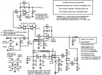
Until I find out if a much longer time-constant is needed, attached is one last DC Servo design. This one's feedback is at -150 dB at 10 Hz, -185 dB at 20 Hz, -199 dB at 30 Hz, and stays below -130 dB over the entire audio frequency range. It has about a 10-second offset-correction time, with about 0.2% overshoot for a 2V offset. It uses only one opamp in the servo loop. Open-loop phase angle at 0 dB gain is about 69.6 degrees.
Attachment is a JPEG image of the schematic.
- Tom Gootee
http://www.fullnet.com/~tomg/index.html
-
Attachments
OK. I actually DID try a WAV music file, as the input signal for an LTspice simulation of a power amplifier with a DC Servo, very similar to the ones in my last-posted schematic. (If you want to use WAV file inputs and outputs in LT-Spice simulations, look in the Examples folder of the standard software distribution, and copy and paste the sources and then right-click on the WAV file name to edit it, in your own schematics.)
Changes I made to the amp/servo circuit: Unfortunately, maybe, I removed the buffers, U6 and U7, to try to speed up the simulation, which was quite slow, even with only 11025 Hz mono WAV file effective sampling rate. I also changed R13 and R17 to 30k, to raise the gain of the power amplifier(s) from about 20 to about 60, so that the peak output voltage's absolute value would be 30v. Then I also changed R12 from 8.2K to 50K, to make the servo correction time about 30 seconds, and to lower the dynamic range of the servo loop (since the offsets were relatively small, compared to those in previous testing). I also changed R2 and R21 to 499 Ohms. And I added 154.55k in series with R6, as well as changing the sum of R1, R4, and R22 to 2.0764 Meg, to get the power amplifier and integrator's offsets very close to zero, with the input grounded.
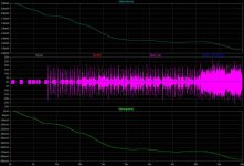
To try make it a somewhat-difficult job for the servo, I chose AC/DC's song, "Highway to Hell", and used a free program called WavePad to edit it down to just the first 60 seconds of the song, for the WAV file (to keep the total simulation time down to around 11000 seconds; yes, it's very slow; Maybe a lower sample-rate for the WAV file would be good to try.).
The attachment is a JPEG image of a transient simulation run's plots of some of the voltages of interest.
At first glance, it looks like the feedback signal might not be "smooth-enough". But, there's something I had not anticipated very well: The DC offset of the _input_ signal, from the WAV file, VARIES, significantly, versus time. This is good, for servo-testing purposes, since it could be true of many sources. And, in this case, it also helps to explain some (but maybe not all) of the apparent "roughness" and variations of the DC servo's feedback voltage's plot: i.e. The servo is attempting to track the changes in output offset that are due to the time-varying input offset.
I guess that I need to learn more about the LT-Spice .MEAS functionality, since it might enable me to totally automate the computation of data, or a metric of some sort, that could be used to quantify the performance of the servo, in tracking the changing offset.
But, for now, I used the plot window's mouse-zoom feature and the plot-averaging feature (i.e. Ctrl-Left-Click on a plot label to average the currently-zoomed portion of that plot), and got averages for specific time intervals, for the input voltage, the output voltage, and the output voltage of the duplicate amplifier that didn't have a servo.
Below is some of the data.
Voltages are in mV, Time Interval in seconds. Voltages are averaged over Time Interval, to give average DC Offset for that interval:
I have not yet made a WAV file from the output. So I haven't yet been able to listen for differences between the input and output. And I don't know, intuitively, whether or not this level of output offset variability would typically be audible.
However, it now appears that a FASTER servo, rather than a slower one, might be better, since it could better-track any effects of a time-varying input offset, and should be able to stop the output offset from varying as much.
That's all, for now.
- Tom Gootee
http://www.fullnet.com/~tomg/index.html
Changes I made to the amp/servo circuit: Unfortunately, maybe, I removed the buffers, U6 and U7, to try to speed up the simulation, which was quite slow, even with only 11025 Hz mono WAV file effective sampling rate. I also changed R13 and R17 to 30k, to raise the gain of the power amplifier(s) from about 20 to about 60, so that the peak output voltage's absolute value would be 30v. Then I also changed R12 from 8.2K to 50K, to make the servo correction time about 30 seconds, and to lower the dynamic range of the servo loop (since the offsets were relatively small, compared to those in previous testing). I also changed R2 and R21 to 499 Ohms. And I added 154.55k in series with R6, as well as changing the sum of R1, R4, and R22 to 2.0764 Meg, to get the power amplifier and integrator's offsets very close to zero, with the input grounded.
To try make it a somewhat-difficult job for the servo, I chose AC/DC's song, "Highway to Hell", and used a free program called WavePad to edit it down to just the first 60 seconds of the song, for the WAV file (to keep the total simulation time down to around 11000 seconds; yes, it's very slow; Maybe a lower sample-rate for the WAV file would be good to try.).
The attachment is a JPEG image of a transient simulation run's plots of some of the voltages of interest.
At first glance, it looks like the feedback signal might not be "smooth-enough". But, there's something I had not anticipated very well: The DC offset of the _input_ signal, from the WAV file, VARIES, significantly, versus time. This is good, for servo-testing purposes, since it could be true of many sources. And, in this case, it also helps to explain some (but maybe not all) of the apparent "roughness" and variations of the DC servo's feedback voltage's plot: i.e. The servo is attempting to track the changes in output offset that are due to the time-varying input offset.
I guess that I need to learn more about the LT-Spice .MEAS functionality, since it might enable me to totally automate the computation of data, or a metric of some sort, that could be used to quantify the performance of the servo, in tracking the changing offset.
But, for now, I used the plot window's mouse-zoom feature and the plot-averaging feature (i.e. Ctrl-Left-Click on a plot label to average the currently-zoomed portion of that plot), and got averages for specific time intervals, for the input voltage, the output voltage, and the output voltage of the duplicate amplifier that didn't have a servo.
Below is some of the data.
Voltages are in mV, Time Interval in seconds. Voltages are averaged over Time Interval, to give average DC Offset for that interval:
Code:
Time Interval     Avg WAV Input         Avg OUT      Avg OUT_NS

10-11               -1.2831              3.7606         63.45
9-12                -1.3936              8.5836         68.176
19-20               -3.0426              39.427         145.47
20-21               -3.1802              39.538         152.31
25-26               -3.5335              13.613         174.19
30-31               -3.6398              2.501          181.3
30.5-36             -3.6275              0.7479         180.97
30-48               -3.7529              1.5848         187.1
35-36               -3.7437              5.7218         185.99
40-41               -4.0689              12.024         201.15
45-46               -3.7659             -1.6601         188.25
48-49               -3.7671              1.6631         190.3
50-51               -4.1814              17.269         205.9
53-54               -4.607               26.481         225.69
55-56               -4.703               21.867         231.19
56-57               -5.6641              17.075         232.12
57-58               -4.553               8.1349         229.66
58-59               -4.7247              2.7743         227.9
59-60               -4.5195             -1.0866         225.78
57.8-60             -4.4995             -0.9678         224.78
I have not yet made a WAV file from the output. So I haven't yet been able to listen for differences between the input and output. And I don't know, intuitively, whether or not this level of output offset variability would typically be audible.
However, it now appears that a FASTER servo, rather than a slower one, might be better, since it could better-track any effects of a time-varying input offset, and should be able to stop the output offset from varying as much.
That's all, for now.
- Tom Gootee
http://www.fullnet.com/~tomg/index.html
Attachments
Hi Tom,gootee said:..I actually DID try a WAV music file, as the input signal.....................
I have not yet made a WAV file from the output. So I haven't yet been able to listen for differences between the input and output. And I don't know, intuitively, whether or not this level of output offset variability would typically be audible.
However, it now appears that a FASTER servo, rather than a slower one, might be better, since it could better-track any effects of a time-varying input offset, and should be able to stop the output offset from varying as much.
I do enjoy sitting back and reading about K's & your labours of love.
I am not at all sure you are reaching the correct conclusion in that last paragraph.
We are trying to minimise the DC output offset of the amplifier.
We are also trying to remove the pass through of the audio signal to the inverting input so that we cannot hear the contaminating pass through signal.
Most importantly, we are trying to make the DC servo inaudible and let the music shine through.
Taking all those into account, I think that if the real audio signal has a varying second by second offset, then that offset is a part of the audio signal and should be presented to the speaker PROVIDED there is no risk of damage to the speaker.
Secondly, the need for speed is to prevent an amplifier induced error from damaging the speaker and maybe from damaging the quality of the wanted audio signal. A slow reaction speed does increase the risk of a delayed correction coming in too late and the speaker coming to some harm. But at the slow speeds you are using the output error you have given us is in the mV or at worst tens of mV. I see no damage limitation need here.
My original view was that correction needed to be of the order of 1second, but having followed this treatise, I am now a believer in the slower is better, upto some sensible limit.
I'm thinking time constants around 5 to 10seconds for the input filter and integrator and slightly shorter (faster) for the output filter. That is somewhat pre-empting my question about the ratio of frequencies to be adopted around the DC servo. I am beginning to suspect that this Q maybe becomes more important for cascaded DC servos where the two (or more) could be fighting against each other. Maybe you should be searching for that missing book.
Who else is conversant with control theory and practice?
Don't retire from the cause just yet, I'm sure there is more than me learning from your endeavours. Importing .wav files!!!!

AndrewT said:Hi Tom,
I do enjoy sitting back and reading about K's & your labours of love.
I am not at all sure you are reaching the correct conclusion in that last paragraph.
We are trying to minimise the DC output offset of the amplifier.
We are also trying to remove the pass through of the audio signal to the inverting input so that we cannot hear the contaminating pass through signal.
Most importantly, we are trying to make the DC servo inaudible and let the music shine through.
Taking all those into account, I think that if the real audio signal has a varying second by second offset, then that offset is a part of the audio signal and should be presented to the speaker PROVIDED there is no risk of damage to the speaker.
Secondly, the need for speed is to prevent an amplifier induced error from damaging the speaker and maybe from damaging the quality of the wanted audio signal. A slow reaction speed does increase the risk of a delayed correction coming in too late and the speaker coming to some harm. But at the slow speeds you are using the output error you have given us is in the mV or at worst tens of mV. I see no damage limitation need here.
My original view was that correction needed to be of the order of 1second, but having followed this treatise, I am now a believer in the slower is better, upto some sensible limit.
I'm thinking time constants around 5 to 10seconds for the input filter and integrator and slightly shorter (faster) for the output filter. That is somewhat pre-empting my question about the ratio of frequencies to be adopted around the DC servo. I am beginning to suspect that this Q maybe becomes more important for cascaded DC servos where the two (or more) could be fighting against each other. Maybe you should be searching for that missing book.
Who else is conversant with control theory and practice?
Don't retire from the cause just yet, I'm sure there is more than me learning from your endeavours. Importing .wav files!!!!
Hi Andrew,
Thanks for sharing your ideas. It is always good to hear from you.
I must agree that things that look like "transient DC offsets" are part of the music, and should not be tampered with.
I also think that any "long-term" DC offset should be removed. (I guess I might have to reconsider, if it can be shown that some music might have a DC offset that is purposely included, for good reason.)
(Everyone please note, too, that speaker and system protection is not the only reason for DC offset suppression. A DC offset also physically offsets the magnetic driver in a speaker, un-centering the speaker cone when there is no signal, and tending to tension it toward a non-centered position during dynamic operation, changing the sound that is produced. I still don't know how significant this effect might be, nor at what levels it might be significant. But I have heard anecdotal evidence that indicates that it "can be" audible, and moreso with some speakers than with others.)
When I first considered what you last said, I thought that perhaps the best solution would be to remove the effects of any input offset from consideration by the servo's integrator, by adding or subtracting (depending on the amplifier) the averaged input signal from the integrator's input, with the integrator's "main" input (from the power amp's output) having probably been resistively divided by the amplification factor, so the magnitudes would match. Simultaneously, one would probably need an open-loop offset control buffer at the input, to zero any offset that was present when no signal was being processed. That would allow the remainder of the servo system design to be mostly free from worry about affecting any "offsets" that were inherent in the music.
That may actually be the best type of approach (But I haven't though about it, much, yet, either.). But I think that almost the same thing could be accomplished by using only the amplifier output for the servo integrator input, AS LONG AS the overall servo time constant could be chosen properly. Perhaps the simulations with WAV file inputs will shed some light on what might be appropriate for a time constant.
It's also possible that a "dual time constant" servo might be the best solution. One part of the system could make sure that the long term average DC Offset was zero, while another part could be much faster but only actively affect the system when the offset was above a certain threshold.
I'll play with the WAV files, some more. (And I'll keep looking for that book.)
P.S. It turns out that recording the output of an LTspice simulation into a WAV file is even easier that using a WAV file for the input. And, "bonus!", it doesn't seem to slow anything down. You do have to remember that WAV files are normalized to a maximum of +/-1 volt, and divide the final output accordingly.
More later.
- Tom Gootee
http://www.fullnet.com/~tomg/index.html
I must agree that things that look like "transient DC offsets" are part of the music, and should not be tampered with.
What sort of things would cause this in music. I am at a loss to think of anything. (Wouldn't it equate to a temporary increase or decrease in air pressure? What kind of speaker could reproduce this?)
And even if there was such a thing, do you honestly think it would be audible?
imho, I think the servos on this thread are much too complicated. It's fairly easy to make inaudible servos with just one opamp.
Every zero-centered sinusoid still spends half of its time above zero and half below zero. So for a single tone, short-enough averaging windows would always provide such cases. Given a large number of sinusoids, all summed together (which any steady-state signal can be described as), I would guess that the probability of the resulting average voltage staying always at zero would be extremely low. And since music is not a steady-state signal, in general, there will also be many uni-polar decaying exponential components, which would be likely, by themselves, to create a non-zero average voltage.
"Inaudible" is not defined well, in my opinion. And certainly some inaudible servos would be better than others. But sorry about the complexity. We were basically just enjoying exploring the "trade space" of the servo-affected parameters, much of the time, and trying to learn.
Last edited:
Music is produced in just about every case by something vibrating, whether it's a string, drum, vocal chord, air, etc. Your answer talks about theoretical things but does not answer the actual question.
"Inaudible" is in my mind pretty well defined. But if you want to sit around here talking about which inaudible servo is better than which other inaudible servo, please feel free. Just that I have no interest, sorry. Just as I have no interest in other inaudible aspects of music reproduction, such as the color of the box you put the electronics in, the meal you just ate or the phase of the moon. Enjoy.
"Inaudible" is in my mind pretty well defined. But if you want to sit around here talking about which inaudible servo is better than which other inaudible servo, please feel free. Just that I have no interest, sorry. Just as I have no interest in other inaudible aspects of music reproduction, such as the color of the box you put the electronics in, the meal you just ate or the phase of the moon. Enjoy.
- Status
- This old topic is closed. If you want to reopen this topic, contact a moderator using the "Report Post" button.
- Home
- Amplifiers
- Chip Amps
- DC Servo question...