I have one (it designed and configured for Aleph 4.0).
See attached schematics.
- R19 represent 24V (DC) relay resistance. C1 is bipolar capacitor or you can use two electrolytic 100u capacitors connected in series (plus poles are connected together and one minus pole is connected to GND, secon is connected to R1).
SW-SPST1 is switch (you can omit it)
Here is my thread:
http://www.diyaudio.com/forums/showthread.php?s=&threadid=130834
Here you can found complex schematics and pictures:
http://www.facebook.com/album.php?aid=158500&l=a5f40&id=1386409150
Attachments
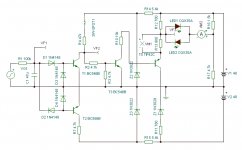
My DC protection circuit topology - explanation
OPT1 electrically isolate audio circuit from soft start circuit and AC detect output from power supply. I used it to prevent ground loops and make thinks easier. DC protection circuit is controlled over this OPT1 by two signals:
AC Detect ¨C this signal is rectified output from both transformer secondary windings. This signal make immediately speakers OFF when amplifier is switched OFF, main fuse is blow, power supply failure on primary site...
Output Delay control ¨C this signal is generated by timing circuit on soft start board. Timing circuit generates amplifier boot (switch ON) sequence: power switch ON ¡ú soft start 10 s ¡ú delayed speakers ON 20 s (timing circuit uses 50Hz frequency from mains; if frequency is 60Hz timing will be shorter with same ratio)
Switch OFF sequence is partially generated by power supply and DC protection circuit topology....:AC detect falls down=switch OFF speakers, then C18 discharge=switch OFF power supply...
Hopefully I explained it clearly")
ping_31140 said:What is the function opt1 ?
OPT1 electrically isolate audio circuit from soft start circuit and AC detect output from power supply. I used it to prevent ground loops and make thinks easier. DC protection circuit is controlled over this OPT1 by two signals:
AC Detect ¨C this signal is rectified output from both transformer secondary windings. This signal make immediately speakers OFF when amplifier is switched OFF, main fuse is blow, power supply failure on primary site...
Output Delay control ¨C this signal is generated by timing circuit on soft start board. Timing circuit generates amplifier boot (switch ON) sequence: power switch ON ¡ú soft start 10 s ¡ú delayed speakers ON 20 s (timing circuit uses 50Hz frequency from mains; if frequency is 60Hz timing will be shorter with same ratio)
Switch OFF sequence is partially generated by power supply and DC protection circuit topology....:AC detect falls down=switch OFF speakers, then C18 discharge=switch OFF power supply...
Hopefully I explained it clearly
- Status
- This old topic is closed. If you want to reopen this topic, contact a moderator using the "Report Post" button.
- Home
- Amplifiers
- Pass Labs
- DC protector ??