FastEddy, found the problem! Still interesting how the superlux still worked, but i have pin 5 & 6 criss crossed on the INA217. So i etched another board and it works fine.
My new question for you is....
What steps are takin to making a quiet pre? No problems what so ever with hum, just some hiss when the gain is up a bit.
Any tips or suggestions to look for?
thanks
My new question for you is....
What steps are takin to making a quiet pre? No problems what so ever with hum, just some hiss when the gain is up a bit.
Any tips or suggestions to look for?
thanks
" What steps are takin to making a quiet pre? No problems what so ever with hum, just some hiss when the gain is up a bit. Any tips or suggestions to look for? ..."
Well, my methods might not be the best or the easiest. And it has been several years (decades?) since I tried to design a complete op-amp circuit from scratch.
Assuming you have a specific plan for this amp (all op-amps circuits, active filters, active gain stages, active signal splitters, etc. are amp circuits = actively adjusting and manipulating a signal). You should of course have a tried and true circuit schematic. This should determine which op-amps, etc. will be used and the approximate board area required, etc. IMOP: too big is better than too small within reason and using single channel op-amps instead of dual or quad op-amps is a plus. (This is one of the reasons I like your project = you added a lot of extra parts that did not interfer with the thrust of the design = a "generic" balanced to unbalanced [conversion] circuit with lots of options. Your board could be used as a summing amp, low pass, band pass or high pass line filter, splitter or XLR I/O w/ unbalanced tap, etc.)
First, as the kids in the DIYAudio power supply arena will tell whoever listens = Determine what the power supply should do (split [+/-] or single [+/0]? How much voltage & power? "phantom power" or not, etc., and consider where to put it.) IMOP: a well thought out power scheme should work in any environment, shielded or not, switching source or not.
Then local filtration considerations = rail caps and snubbing caps location, etc. related to the physical layout of the circuit (board). Passive parts locations = what goes where, etc.
The above can all be done with software, ahead of a breadboard construction. A whole lot of it comes easily, almost naturally, after you have done it a few times. (When I was doing this regularily, I relied on op-amp cookbook sources from the op-amp gurus at Analog, National, Fairchild, etc., instead of reinventing the wheel repeatedly. My favorites were/are Don Lancaster, but he doesn't reprint his op-amp cookbooks anymore [ http://www.tinaja.com/books/bkdons.asp ] and Walter Jung [ http://www.analog.com/en/cList/0,2880,759%5F%5F42,00.html ] and more recently, Bob Pease [http://www.elecdesign.com/Departments/Index.cfm?AD=1&DepartmentID=6 ])
Tools needed to "fix" an analog breadboard design: A decent 'scope, decent signal generator or signal source and a cheap volt meter. I have never spent more than US$100 for any of the above. (Surplus military tube 'scopes are also a great source for tubes and precision parts for amp projects. Try for 10 megaHtz range, dual channel. I have two that work and several junked for parts.)
Once the breadboarded circuit works reasonable well, noisey or not, you can consider making some boards, adding (as previously noted) extra pads & holes for alternate sized components like bigger and smaller: electrolytic caps, resistor types, off board components, etc. Copper trace circuitboards are another technology altogether, so consult some more gurus, then make one or two ...
The last step, posting your results, here or elsewhere, is the one you have taken first ... that's not really a problem as this is the way most DIY types do their projects = bass ackwards
Your "hissing" noise is either coming from the power supply or you have the gain too high on one of your op-amps ... these op-amps are all supposed to be approximately unity gain or just a few db gain = not big ... and a high gain amp will always be capable of picking up pop corn noise and amplifying it = hissssssss
new and improved version!!!
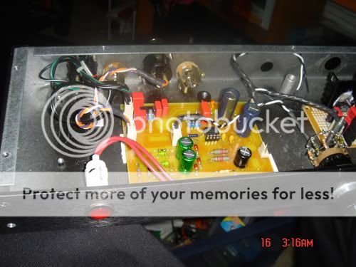
main purpose was to save some cash if i make some boards. and also so i can fit it in a 1RU chassis and still have room to fit a compressor circuit that i plan on doing. Ill put up a pic or two in a little. i etched a board, but havent done any listening test yet.
eddy what do you think?
main purpose was to save some cash if i make some boards. and also so i can fit it in a 1RU chassis and still have room to fit a compressor circuit that i plan on doing. Ill put up a pic or two in a little. i etched a board, but havent done any listening test yet.
eddy what do you think?
Fixed it all? How many are you going to make ?? Can I have five?? I will use one as base for a summing amp and low pass for sub woofer with XLR or unbalanced input), the rest for XLR to unbalanced conversion (line receivers) for feeding remote mono-block amps from XLR mixer.
Also, consider that the power supply may vary from project to project so make all caps capable of +/- 24 VDC (with or without the 48 volt pahntom power) for now = > 50 volt rated. You can change this later, but prototypes should be able to take a lickin' and keep on tickin' ...
And another thing, Re: the power supply: The use of +/- 24 VDC output from your transformer / bridge rectifier on the power supply board will allow you to regulate down to +/- 15 with linear regulators (LM317?) for the op-amps and also have a source for that (optional) 48 volt phantom power = simpler transformer = a single secondary winding of ~ 32 to 34 VAC ...
(Be prepared for more modifications, so don't make too many yet.)
"Anything worth doing is worth doing for money ..." - Alfred E. Newman / Mad Magazine ...
How much ?? each? six-pack of bare boards? (The rule of thumb for electronics manufacturing is "bag o' parts" times three, but you are doing prototypes here, so just cover your "out of pocket" costs.)
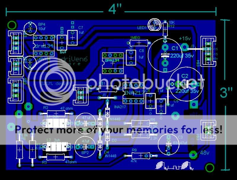
Things I like about this layout:
* 48 volt phantom power routed around outside edge of board w/ ground path isolation from lower voltage interior.
* Room for big or smaller input DC blocking caps and alternates for power line filter caps.
* alternate locations for I/O connections.
* signal paths surrounded by perimiter ground plane = good CMRR.
* reduced copper etching = nice wide traces, not too crowded.
* only three jumpers = single sided board. (It might be possible to use double sided board material if you had a layout for the back side ready to go, but I would keep the jumpers and not try to put power / signal traces on the back side = makes for easier repair, reduced solder steps, etc., but still allows the back side copper to act as shielding =
...
Still missing (for my pecular design needs):
*additional through holes for "close coupled" 0.001 to 0.010 uF plastic snubbing caps (parallel to C6, C7, C8 electrolytics - C4 snubber exists). (I will probably have to mount these on the backside, right across the op-amp power pins.)
* No copyright notice and no label of purpose ("XLR to UnBal." could go right between those input inductors.)
* You could save some silk screening costs and errors by "etching" the labels in the copper ... no need for op-amp type labels (except pin#1 &/or 8 polarity labels) as this board can use a variety of op-amps ... make your prototypes with 8-pin mini-DIP sockets (the snubbing caps will take care of any preceived socket issues).
* Only two mount holes ... there is room for two more @ each corner. (Size should conform to those cute plastic computer board mount types or #6 or #8 screws ... leaving room for oversized washers, nuts, etc. (Top left may need some more clearence.)
... got the latest schemo?
eddie i will send you a couple of etched boards in the next week or so if you like. you can run some test (on your free time) and make suggestions for improvement. cause really i'd rather not have a board made that will just get chopped up.
i'll make some room for some parallel plastic snub caps.
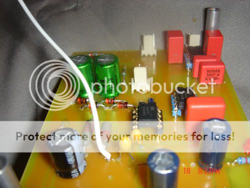
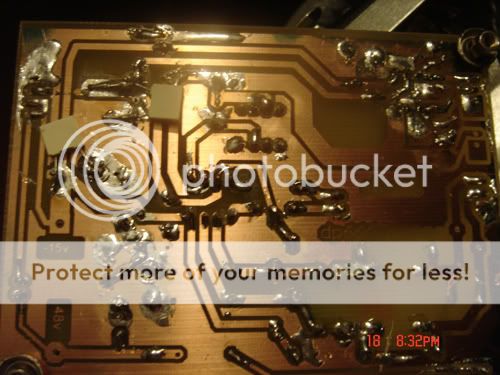
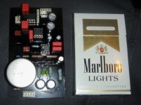
here is a few shots of it so far.
and make suggestions for improvement. cause really i'd rather not have a board made that will just get chopped up. i'll make some room for some parallel plastic snub caps.
here is a few shots of it so far.
Done ... I may also use this board with minor mods as a mono sub woofer amp input from stereo pre-amp. See http://www.diyaudio.com/forums/showthread.php?postid=1191899#post1191899
Several TI chips for this have just arrived this AM ...
Several TI chips for this have just arrived this AM ...
great i cant wait to see your outcomes.
i just got your shipping address today. i got the blank pcb's yesterday but havent etched them yet. tomorrow.
say eddy im getting alot of noise. more like noize with a "Z". Its an electrical noise kinda like a zapping/ticking noise. I have the power pins on the ina217 bypassed w/ tantulm(1uf) and wima's(.1uf), and the the lytics on the power input on the board are bypassed with .1uf wima's. ???
i used 1n5058(a)" i believe", diodes instead of the 1n1448 cause i was out of them. could that be a cause of extra noise? or do you think its the power supply? i read somewhere that 78xx,79xx are loud and would be better to use 317 and 337's. or could it be the bridge rectifier i used? it was a cheap one from radio shack. other then that all the components are of high quality caps are all FC's or Hfq's and wima's. and resisters are all hand matched. any ideas?
Noise source possibilities:
Cold solder joints or solder bridges or maybe you are using silver solder of greater than 4%. Advise using old fashioned 60/40 - Tin/Lead solder on prototypes and hitting all suspect joints again. (No offence intended, but from your pictures, I would say this cold joint question is a higher probability.) You don't need to remove the old solder except where it is puddled up to a large extent, just add a small amount of regular solder to each joint letting the iron "pull" or remove the excess.
Bad caps?: For prototypes I always use "fresh" new (unused) capacitors. (The stuff I have laying around in my shop can be decades old and the cap leads may have considerable corrosion = same results as cold joints ... ) Also, put the Tantalum caps on the shelf and use quality electrolytics until you are sure about quality and usage = Tants are best for the power supply board, not close coupled to op-amps. Tants also have questionable quality, unless you are familiar with the manufacturer ... lots of boots, lots of mislabels and unreadable labels. Tantalum capacitors are going out of fashion for more reasons than environmental = expensive, soggy and hard to light.
Diodes for the input clamps?: leave 'em out until the circuit is clean, noise free and running properly, then add 'em back and check again. (Germainum diodes won't work as input clamps but may be mislabeled as silicon types. Schottky diodes can be used with caution as many voltage restrictions apply = silicon diodes are best for now = later. Ordinary "small signal" silicon diodes will work as clamps. ... )
The bad rap about the 78xx / 79xx is usually traced back to the support components, not the chips ... carbon resistors, under sized electrolytics, etc. If you feel that the 78xx/79xx are a problem, use the '317 / '337 type instead = no worry, no concern = improved confidence = whatever blows your skirts up ...
Your periodic "zzzzt" noise is puzzling, possibly caused by an oscillation in a regulator or an op-amp. Others here @ DIYAudio may have a better idea about this. My guess is that the above will solve it ... do your repairs in the order suggested above, priority being given to solder questions ...
Cold solder joints or solder bridges or maybe you are using silver solder of greater than 4%. Advise using old fashioned 60/40 - Tin/Lead solder on prototypes and hitting all suspect joints again. (No offence intended, but from your pictures, I would say this cold joint question is a higher probability.) You don't need to remove the old solder except where it is puddled up to a large extent, just add a small amount of regular solder to each joint letting the iron "pull" or remove the excess.
Bad caps?: For prototypes I always use "fresh" new (unused) capacitors. (The stuff I have laying around in my shop can be decades old and the cap leads may have considerable corrosion = same results as cold joints ...
) Also, put the Tantalum caps on the shelf and use quality electrolytics until you are sure about quality and usage = Tants are best for the power supply board, not close coupled to op-amps. Tants also have questionable quality, unless you are familiar with the manufacturer ... lots of boots, lots of mislabels and unreadable labels. Tantalum capacitors are going out of fashion for more reasons than environmental = expensive, soggy and hard to light.Diodes for the input clamps?: leave 'em out until the circuit is clean, noise free and running properly, then add 'em back and check again. (Germainum diodes won't work as input clamps but may be mislabeled as silicon types. Schottky diodes can be used with caution as many voltage restrictions apply = silicon diodes are best for now = later. Ordinary "small signal" silicon diodes will work as clamps. ... )
The bad rap about the 78xx / 79xx is usually traced back to the support components, not the chips ... carbon resistors, under sized electrolytics, etc. If you feel that the 78xx/79xx are a problem, use the '317 / '337 type instead = no worry, no concern = improved confidence = whatever blows your skirts up ...
Your periodic "zzzzt" noise is puzzling, possibly caused by an oscillation in a regulator or an op-amp. Others here @ DIYAudio may have a better idea about this. My guess is that the above will solve it ... do your repairs in the order suggested above, priority being given to solder questions ...
thanks eddy, i will do the repairs as suggested. the tantulum caps are Nemco, but i will sub them out for lytics right now. the "zzzt" is not periodic, its constant, low volume. But now that you mention it, it very well could be a solder joint. I had to lay down the solder cause i broke my last small drill tip and had to resort to a bigger size.
- Status
- This old topic is closed. If you want to reopen this topic, contact a moderator using the "Report Post" button.
- Home
- Amplifiers
- Solid State
- dc output control loop