In this application note, you can find another good example of a servo drive.
http://www.national.com/an/AN/AN-1192.pdf
And what about the first sound test of your amp, Maxw?")
Franz
http://www.national.com/an/AN/AN-1192.pdf
And what about the first sound test of your amp, Maxw?
Franz
Vikash said:If it bothers you than you can adjust the resistance from signal in to ground, or perhaps try the Ci cap as shown on the National schematic.
Yes, this can be done and lowers DC to very low values.
Max, I suppose you are testing the amp without signal, no source connected.
You have on the input a 22k resistor to ground.
Is this an integrated amp you are doing or a power amp?
In case of an integrated amp, did you try connecting there a pot and measure DC again?
In case it's a power amp, have you tried other values at the input to ground instead of 22k?
Oh,
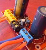
heatsink you have there.
Haven't done a sound test yet, i was waiting until I got this sorted first. That looks kind of complicated, I'll try it as a last resortFranz G said:In this application note, you can find another good example of a servo drive.
http://www.national.com/an/AN/AN-1192.pdf
And what about the first sound test of your amp, Maxw?
Franz
carlosfm said:
Yes, this can be done and lowers DC to very low values.
Max, I suppose you are testing the amp without signal, no source connected.
You have on the input a 22k resistor to ground.
Is this an integrated amp you are doing or a power amp?
Yes, no signal, no source.
I have made a temp external volume control for testing out of a 10k Taiwan alpha log pot but it the end it will be powered by a buffered preamp so it wont be integrated
carlosfm said:
In case of an integrated amp, did you try connecting there a pot and measure DC again?
In case it's a power amp, have you tried other values at the input to ground instead of 22k?
Oh,
You just mean a pot between Input ground and input +?
No I haven't tried any other values yet, will do.
Vikash said:If it bothers you than you can adjust the resistance from signal in to ground, or perhaps try the Ci cap as shown on the National schematic.
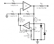
See my attachment, is that the right way to implement Ci? It what I figured from looking at the diagrams and Brians userguide.
Thanks for your help guys
Attachments
maxw said:See my attachment, is that the right way to implement Ci? It what I figured from looking at the diagrams and Brians userguide.
LOL guess not
Just tried it and my 10 Ohm resistor across out went up in smoke

maxw said:See my attachment, is that the right way to implement Ci?
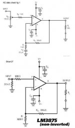
See LM3875 datasheet, page 1, figure 1.
I don't know if on Brian's schematic it's R3.
If you post the schematic I'll tell you if it's ok.
Sorry, too busy to search for it now, I'm finishing my new pre.

Oh, forget the resistors across the output for now, measure DC without anything connected.
What DC values do you have on the output now, with Ci?
carlosfm said:
See LM3875 datasheet, page 1, figure 1.
I don't know if on Brian's schematic it's R3.
If you post the schematic I'll tell you if it's ok.
Sorry, too busy to search for it now, I'm finishing my new pre.
Oh, forget the resistors across the output for now, measure DC without anything connected.
What DC values do you have on the output now, with Ci?
I have attached a pic with both schematics.
I dropped the resistors on the output and its the same.
My resistor burning up must have been because of a bad connection with my test board because the IC is just sitting in the wholes, not soldered.
So I retried with 22uF electrolytic as Ci and got a DC offset of 2mV!! That must be good right providing I've stuck it in the right place?
Attachments
I did a listening test today with a Sony CDP, 10k pot and my DIY 2 way speakers. I added the Ci cap as in the above attachment to the unit that had 80mV DC and then was 1-3mV. The other unit I used was the one with no Ci cap and it had an offset 44mV and 20mV when all connected up to pot etc.
So I have tested the Ci cap on two units now and in both cases it reduced DC offset to 1-4mV. So why doesn't everyone use it? does it affect the sound? (I couldn't tell with one channel using it one not)
So I have tested the Ci cap on two units now and in both cases it reduced DC offset to 1-4mV. So why doesn't everyone use it? does it affect the sound? (I couldn't tell with one channel using it one not)
So I have tested the Ci cap on two units now and in both cases it reduced DC offset to 1-4mV. So why doesn't everyone use it? does it affect the sound? (I couldn't tell with one channel using it one not)
Because, as some of us have found, lower DC offset does not necessarily mean better sound, in fact I found the opposite was true.
Try both and hear for yourself.

maxw said:So I retried with 22uF electrolytic as Ci and got a DC offset of 2mV!!
maxw said:I did a listening test today with a Sony CDP, 10k pot and my DIY 2 way speakers. I added the Ci cap as in the above attachment to the unit that had 80mV DC and then was 1-3mV.
maxw said:So why doesn't everyone use it? does it affect the sound? (I couldn't tell with one channel using it one not)
You can bypass the 22uf cap with a 100~150nf poly cap.
Let it
-in for some days.If you don't want do make an inverting amp (with buffer, preferably), with NI this is the way to go IMHO.
What's debatable is what has more effect to the sound?
- 80mv DC
or
- Ci caps?
Your speakers may not work so well with 80mv DC.
But the effect of the Ci caps, if they are decent quality, is minimal if not undetectable.
carlosfm said:But the effect of the Ci caps, if they are decent quality, is minimal if not undetectable.
Well I cant hear the difference and I like things that are technically good so I will use Ci on my GC. Cool.
One last Q though, I have used a cheap generic cap that is 35V, cost 50c. The only place I can get better ones in NZ is RS so do you think Elna Starget (for example) caps would be worth paying $10-$15 for? or shall I just use generic low ESR ones?
maxw said:
Well I cant hear the difference and I like things that are technically good so I will use Ci on my GC. Cool.
One last Q though, I have used a cheap generic cap that is 35V, cost 50c. The only place I can get better ones in NZ is RS so do you think Elna Starget (for example) caps would be worth paying $10-$15 for? or shall I just use generic low ESR ones?
Like I said on another thread, according to an article published in Electronics World and Wireless World, try a bipolar capacitor as feedback DC block. Something reasonable good, not any speaker cap you may find around.
If the feedback resistors you are using are large, particularly the small one, you can even get to use film caps. Something like 2 x 4.7uF should not be expensive to arrange.
Carlos
I am having dc offset problems as well (about 60mV on both outputs). I don't have any .22 uF caps on hand but I do have some 0.1uF caps on hand ( http://www.partsexpress.com/pe/showdetl.cfm?&DID=7&Partnumber=027-452 )
Can I use these for Ci?
My gainclone is exactly like noninverting "classic" circuit at http://www.geocities.com/rjm003.geo/rjmaudio/diy_gc.html excpet I don't have R5 and C5 on the outputs.
Thanks.
Can I use these for Ci?
My gainclone is exactly like noninverting "classic" circuit at http://www.geocities.com/rjm003.geo/rjmaudio/diy_gc.html excpet I don't have R5 and C5 on the outputs.
Thanks.
maxw,
Did you take offset measurements with the input conected? Because if input is connected to a source, your readings might change again. Same goes for heat, aging effect.. etc.
Dont worry too much about offset, especially if its low like in your case. It will change again after sometime.
I (and many others?) personally disgust of having Ci there in the circuit. What I would suggest is to try as many chips as you could to find a low-offset pair.(like what gaincard guys did?)
skyraider said:maxw,
Did you take offset measurements with the input conected?
I think I did but it was long ago, cant remember now
Im sure this problem will crop up again with my LM3886 and LM4780 amps but I wont be so concerned this time
Im glad someone else found this thread usefull too.
- Status
- This old topic is closed. If you want to reopen this topic, contact a moderator using the "Report Post" button.
- Home
- Amplifiers
- Chip Amps
- DC offset problem