Hi Tief, if there is no load that rectify the mains in some manner or other, in other words draw more current from one half cycle than the other in your home, you will not have a buzzing transformer.
There are many sources causing this problem which includes light dimmers, hair dryers, some fridges, some wall warts and it is not always noticeable, only an irritation at times, but no cause for concern.
I have had such a trap on my amplifiers for years with caps connected back to back without any failure.
Andrew has mentioned in some earlier post that as long as you do not DC reverse bias an electrolytic cap with more than a volt or so, it will not be damaged at all.
"Hi Tief, if there is no load that rectify the mains in some manner or other, in other words draw more current from one half cycle than the other in your home, you will not have a buzzing transformer. "
Not true.
Any house on the same line transformer will cause an imbalance. If my neighbor uses his/her hair dyer it will make my torroid hum.
Not true.
Any house on the same line transformer will cause an imbalance. If my neighbor uses his/her hair dyer it will make my torroid hum.
"Hi Tief, if there is no load that rectify the mains in some manner or other, in other words draw more current from one half cycle than the other in your home, you will not have a buzzing transformer. "
Not true.
Any house on the same line transformer will cause an imbalance. If my neighbor uses his/her hair dyer it will make my torroid hum.
That is debatable, only if you have a drop feed from an overhead reticulation system.
All of the legacy devices that used series power diodes to lower their output are only used intermittently. That is devices like hair dryers, water heaters, space heater and cooking stoves. The effects of these high power units could make it from house to house, but all the units are intermittent and your hum/buzz should come and go.
Newer equipment with Switch Mode Power Supplies might operate 24 hours by 7 days, but I think that the interference range is much smaller.
Newer equipment with Switch Mode Power Supplies might operate 24 hours by 7 days, but I think that the interference range is much smaller.
By the most user's that I know, this unwanted toroidal mechanical hum is only temporary present and not always. In my own aera this hum is present only in the late evening and during the night hours. In other region this hum is mostly present only during the day.
Last edited:
Yes, most residential areas in the USA are reticulated like veins of a leaf. There will be a common centrally located transformer feeding several homes from a common transformer secondary.
The noise is intermittent, as when you or your neighbor uses his hair dryer, or halogen floor lamp on the 'low' setting, and the noise clears when the device is shut off.
The noise is intermittent, as when you or your neighbor uses his hair dryer, or halogen floor lamp on the 'low' setting, and the noise clears when the device is shut off.
quote
The noise is intermittent, as when you or your neighbor uses his hair dryer, or halogen floor lamp on the 'low' setting, and the noise clears when the device is shut off.
I can agree 100% with that. I can hear noise when the neighbors AC turns on, mine turns on, refrigerator turns on, basically just about everything that result in noise on the system.
Have played with the magical AC boxes guaranteed to get rid of all the hash on the AC line and some do work somewhat but at what price?
Learn to live with the noise and be happy that your not suffering in a brown or blackout.
Jason said:Hi Mohan,
I live in London with probably some of the worst mains ion the world (6% distortion and very truncated sine wave). Over the years I have done the following.
1. Had Aviel Lindberg design 3 kVA special toroids with overarted everthing and with resin wrapping. This didn't work and the units hums with what's happening in the mains. The LC unit doesn't work. Enclosing this in a large steel box makes the humming worse if the top is on.
2. Bought Hi Fi News Ben Duncan 1 kVA units. They work, but have quite a high voltage drop between load and no load.
3. Used 5 kVA computer ultra isolators and the positively sang. They are fine when placed outside in the supply room and are permanently connected to one of the audio sockets.
4. Heard ac regeneration and they really sound good, but expensive.
5. My advise is not to place any significant impedance to the audio units. 10 Ohm slo blos really degrade the sound. Try it on Assemblage units with these fuses and you will know what I mean. You do so at your own risk and should only do so if you REALLY know what you are doing.
Very intersting observation.
this brings me to follow questions:
1) what is therefore the reason (hair dryers, dimmer and similar stuff alone cannot create such condition)
2) is this value of 6% more likely in the evening or while the daytime ?
3) Which DC value I must add to an undistorted mains sine wave curvature to get the same level of mechanical noise?
4) are there pics anywhere here from London's mains curvature of this very truncated resp. clipped sine wave?
Last edited:
I guess, in all cases, where the usually DC blocker don't provide the expected success, the residual distortion is too large. In such cases an easy solution like the dc filter topology don't exist - as I know.Hi,
I'm shooting from the hip here so I could be wrong.
The DC that creeps into our mains supply is not a pure DC instead of an AC signal.
It is a DC superimposed on an AC waveform with a lot of distortion thrown in. In fact that distortion is the clue.
The AC waveform is distorted to such an extent that the tops of the waveforms can be SEEN to have flattened tops due to other loads taking non linear current. It is the asymetrical flattening that gives an effective DC component to the AC waveform. The negatives do not balance out the positives equals net DC.
Stopping a voltage/current as it passes the zero crossing will not remove the distorted waveform. The flattened waveform will still exist and still show it's effect as distortion.
Could there be another effect that the diodes are using that reduces the hum?Any counter argument?
It would be interesting to know, if there is a hum-free transformer by present DC, whether this transformer is also hum-free, if there are large second harmonics on the mains.
Are there this pics anywhere on the web for download?I've done some measurements that show what's really hapening when you connect a transformer to mains
Using a lowpass filter [100k + 47uF] I have measured about 50mV average over time of DC on my mains supply
I also have an old electric heater that in half-power mode uses a diode in series with the heat element to pass only half of the mains waveform. When I plug this heater in half-power mode I get an additional 1V of offset on mains supply
To test the need and the efficiency of DC filtering, I've done some measuremens of the current through the primary of a 750VA toroidal transformer
This oscillogram shows what happens when I connect the transformer to mains and let it deal with the 50mV DC offset
An externally hosted image should be here but it was not working when we last tested it.
Blue trace is mains waveform at 100V/div [230V AC], it looks more like a clipped triangle wave instead a sine wave due to the line inductance limiting the slew rate and all the rectifiying applications consuming all the current only during the peaks [30% of total time]
Red trace is the current through the primary at 200mA/div. Transformer saturation towards the negative side is evident, reaching 350mA peak of leakage current. The transformer buzzs slightly due to the saturation
The noise present in the current waveform is common mode and was suppressed in further measurements adding a common mode filter between mains and measurement point
The second oscillogram shows what happens when I plug the electric heater in half-power mode
An externally hosted image should be here but it was not working when we last tested it.
Red trace this time is in 2A/div so the leakage peak current exceeds 6A. The transformer is heavily saturated towards the upper side and buzzs loudly.
The third oscillogram shows what happened when I placed a DC filter consisting of two 1000uF 16V and some diodes in series with the primary
An externally hosted image should be here but it was not working when we last tested it.
This time, red trace is 20mA/div and shows the small leakage current due to both the magnetizing inductance and the parasitistic capacitance between adjacent turns. The transformer is no longer saturated and performs silently
the fourth oscillogram shows the induced voltage in a loop of wire of 10cm diameter placed vertically, paralell and 1cm away from the transformer [placed horizontally] obtained when the transformer was saturating with more than 6A peak [with the electric heater plugged]
An externally hosted image should be here but it was not working when we last tested it.
The red trace is 2mV div and shows the induced voltage in the loop of wire
That measurement demonstrates that when a 50-60Hz transformer is saturating, it produces electro-magnetic-interferences that induce noise voltages on everything in the nearhood
Actually, I think that +-5mV of low frequencies induced in a loop of wire of 10cm diameter near the transformer is a serious thing since this EMI is at audio frequencies, it's not RF so it's 100% audible and it may be happening in all your transformers
In the other hand, all the tests were performed with open secondaries but if we add load so that primary current has peaks of 6A, then the EMI radiated would be the same or higher
With load, the EMI is produced due to flux in the leakage inductance, resonances due to parasitistic inter-turn capacitance, RF ringing due to diode turn-off characteristics and the fact that the peak current through the transformer is 3 times or more the average DC current after rectification
In conclusion : Rectifiying the output of 50-60Hz transformers produces EMI as any SMPS does and this phenomena gets aggravated when the transformer is saturating due to direct connection to mains without a DC filter
50-60Hz transformers are nothing but big, bulky and crappy antennas
Last edited:
Would this EPCOS filter work
Hi all,
Newbie to diyAudio here. I've been struggling with transformer hum from my new integrated amp (classic 700 VA transformer), I also have a Denon 3808 AV receiver (also classic transformer) that suffers from the same hum. Both are connected to different simple EMI/RF mains filter blocks. I was wondering whether this EPCOS filter would do the trick, installing it on the mains input side of the mains filter block or behind it on the output side. This Epcos filter costs about 50-60 eur. Can any of you gurus comment? There seems be a lot of different solutions here. What happened to Nelson Pass's solution on page 1 of this thread? I mean, Nelson Pass!!! I like his solution for its utter simplicity, OTOH I have a morbid fear of exploding caps...
Thx!
Marcie
Attachments
no.
The Epcos filter linked are interference attenuation filters.
A DC blocking for Mains AC is quite different.
BTW,
you can buy IEC mains input socket with suppression filter built in for just a few dollars.
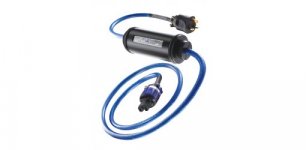
Thanks Andrew, I thought as much. I know about the filter input sockets but I can't find any that will do DC filtering. There's a mains cable from Isotek that has an in-line DC filter (the Synchro) but it is really expensive. See attachment.
Cheers,
Marcie
Attachments
") Which method should I use?
Which method should I use?
As long as it is in series with the transformer primary it all works the same, use either leg.
It is easiest to use a single bridge rectifier in series with one leg, but if your mind demands symmetry you could use four individual diodes, two in one leg, two in the other. See post #13 for the general idea. You may want to use two capacitors in parallel per diode pair, as per the Bryston method, or none as per the Crown method. The Crown is a huge KW rated amplifier, so two bridges are used in parallel, only one needed for most amplifiers.
It is easiest to use a single bridge rectifier in series with one leg, but if your mind demands symmetry you could use four individual diodes, two in one leg, two in the other. See post #13 for the general idea. You may want to use two capacitors in parallel per diode pair, as per the Bryston method, or none as per the Crown method. The Crown is a huge KW rated amplifier, so two bridges are used in parallel, only one needed for most amplifiers.
Last edited:
Hi,
even in Belgium you´ve got a live and a neutral wire just like in the Netherlands. Only very old systems have two times 127V but I don´t think they exist anymore. The neutral wire is connected to the safety earth where the mains enter the house.
The only thing that is missing in Belgium and Holland is the safety earth on every outlet (you only need them in the bath, cellar, kitchen etc.).
For my Father's stereo I connected the mains in the cellar to get a safety earth for the balanced AC transformer.
William
- Home
- Amplifiers
- Solid State
- DC filter