One great application for an electronic load is measuring output impedance plot of SMPS and load transient, also good for tuning linear regulators. If I had to design such an electronic load I would do it with builtin 10 bit ADC and a few scales selected with CMOS switches, possibly processing AC and DC components separately, to be able to use different scales and process small AC on top of DC, this would allow measuring AC output impedance of a PSU under different DC load levels. Or it can be done brute force mode, higher bit depth, higher cost...
In general, higher bit depth and FPGA is only sensible either for audio and video processing (precision signals targeted to please and calibrate human senses), or for rare medical scanning equipment, or for rare scientific measurement equipment (like precision measurement of properties of materials or chemical reactions in research), or for rare industrial process control applications where both high speed and high precision are needed.
In general, higher bit depth and FPGA is only sensible either for audio and video processing (precision signals targeted to please and calibrate human senses), or for rare medical scanning equipment, or for rare scientific measurement equipment (like precision measurement of properties of materials or chemical reactions in research), or for rare industrial process control applications where both high speed and high precision are needed.
Last edited:
What type of tests or measurements require an electronic load with 0.1% precision in current or resistance setting?
Is there a situation where a load sweep and interpolation is not enough for a measurement or test?
Of course you can argue that you want to experiment with higher precision chips and FPGA, and I would agree, but learning higher precision or FPGA is tightly associated with learning certain few applications where it is needed.
Hi Eva. yes there is, I want to test small to medium capacity batteries, basically show measure discharge curves up to ~3.0A approximately at 0.5% accuracy.
Attached is a manual for a BK precession 8500, as you can see for battery applications it is well suited to track battery discharge, at accuracy maybe I should have mentioned this). For load sweeping, I do agree that absolute accuracy isn't key. This project for me personally is geared around learning key area's around precession analog circuits that is software controlled.
https://bkpmedia.s3.amazonaws.com/downloads/manuals/en-us/85xx_manual.pdf
Last edited:
I think I could get that 0.5% in battery measurement, or more, with built-in 10 bit ADC (and trimming maybe). It's a matter of producing white noise with a pair of transistors, injecting a couple of LSB of noise into the ADC, sampling at the highest frequency allowed by PIC processing power, and summing or averaging readings in a higher bit depth accumulator or IIR LPF. Oh, wait, but this is not conventional C programming, it is real-time signal processing, as complex to do in ASM as in C, and saves a lot of resources haha
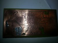
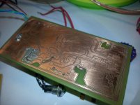
The weekend is over, This is the last entry for now, I have managed to develop the board at home, its been a while since vie created a board out im out of practice, anyway this isn't bad considering I used a UV nail lamp 
Attachments
Last edited:
I think I could get that 0.5% in battery measurement, or more, with built-in 10 bit ADC (and trimming maybe). It's a matter of producing white noise with a pair of transistors, injecting a couple of LSB of noise into the ADC, sampling at the highest frequency allowed by PIC processing power, and summing or averaging readings in a higher bit depth accumulator or IIR LPF. Oh, wait, but this is not conventional C programming, it is real-time signal processing, as complex to do in ASM as in C, and saves a lot of resources haha
Resource reduction at its best.Resource maximization actually. Who taught you to use ADC in brute force mode and expend more in parts to avoid developing an optimum application precision compromise? A toxic master for sure.
I used the same ADC as the one in the old BK8500, here are pictures of the new version maybe you will have better understanding decoding the design.
https://hiveminer.com/Tags/bk,precision/
Thanks for the pictures. Analyze the design choices. Note that they cannot afford designing a SMPS, so a bulky 50/60hz transformer is used instead. Also note they cannot afford designing a control interface based in a modern color LCD display and a pushbutton encoder, so those ancient alphanumeric displays and keyboards are used instead. Note the usage of small electrolytic capacitors, this equipment has programmed obsolescence builtin, so longer life is not an argument. Design team stuck at some obsolete practices. Ditto for the 16 bit ADC and FPGA, I think. No need for these chips for controlling just a single DC load. This is about "engineers but not inventors", or the partial failure of educative system, like losing competitive creativity in the process.
Note that they cannot afford designing a SMPS, so a bulky 50/60hz transformer is used instead..... Note the usage of small electrolytic capacitors, this equipment has programmed obsolescence builtin, so longer life is not an argument.
Why would this type of product 'need' a smps, and how can you tell that the electrolytics aren't going to last - this is all just for powering controls and fans.
Reactance, if your target is for battery discharge capacity performance testing then be aware that cycle by cycle performance comparison is a lot more than just looking at Ah or Wh values. Measured capacity of the same battery can typically bounce around between cycles, and trend up and down in an ad hoc manner before finally trending down, and that's in a lab environment with temp controlled conditions (such as a water bath) and with specific recharge and rest conditions. As such even 0.5% absolute accuracy of Ah or Wh (which would need V sense probing) is down in the noise for comparison purposes.
During initial testing it can be well worthwhile trying to get as close a measurement of FET junction temp as possible for max dissipation condition, as a way of estimating how much margin you have between Tj and Tj max, and design in some thermal feedback derating from say a PTC.
Oh, yes. The danger in that field are the Chinese and other emerging cultures. Everyone wants new equipment to be low-cost, high-performance, light-weight and pleasant to use. So, while in other cultures (where the 1st generation of industrial electronics designers is almost gone and the 2nd generation for some reason missed the seed of invention) people is struggling with cult to iron, in emerging cultures someone will invent a way to do it with less natural resource usage (the 1st generation of industrial electronics designers always originates from the seed of invention) and in the end this is the way that will prevail. Recession in English speaking countries is related to that phenomena.
Or is it the accuracy of the operating point to a preset reference value (eg. set operating point current to be with 0.1% of 1.00A, but not worry about voltage as that may vary due to temp comp of power supply or mains voltage variation, or as a battery discharges).
hi trobbins
Using preliminary figures, I have selected to obtain 0.1% for both voltage and current. I know this is possible because the components I'm using are designed for the stability and accuracy for applications like this.
For example the voltage reference I will is a ADR421.
http://www.analog.com/media/en/technical-documentation/data-sheets/ADR420_421_423_425.pdf
As for measurement equipment, I own a Keysight 34461A bench meter with data logging capability so I can easily plot this when I get there.
34461A Digital multimeter, 6 ½ digit, 34401A replacement, Truevolt DMM | Keysight (formerly Agilent?s Electronic Measurement)
By the way this isn't for "any clients", its purely a personal R&D project and if it works out well, i'm releasing the plans and firmware publicly.
I think I could get that 0.5% in battery measurement, or more, with built-in 10 bit ADC (and trimming maybe). It's a matter of producing white noise with a pair of transistors, injecting a couple of LSB of noise into the ADC, sampling at the highest frequency allowed by PIC processing power, and summing or averaging readings in a higher bit depth accumulator or IIR LPF. Oh, wait, but this is not conventional C programming, it is real-time signal processing, as complex to do in ASM as in C, and saves a lot of resources haha
Eva, If you have time do post some figures here if you have time using your suggested technique, at this moment in time I don't have the time to dive into this area of optimization you seem to have alot of R&D time, I still maintain that using an external ADC has many advantages in this application as im pressing for time and probably will revisit your suggested technique, just not now.
I found a service manual of a 300Watt Agilent that might resonant with your design philosophy as it dates back 10 years (not to say that its bad design) its just based on more simpler parts. for my analog design I used some idea's comes from this design.
http://ridl.cfd.rit.edu/products/manuals/Agilent/power%20supplies/CD1/service/6060ser.pdf
Last edited:
Good reference!For example the voltage reference I will is a ADR421.
http://www.analog.com/media/en/technical-documentation/data-sheets/ADR420_421_423_425.pdf
I went with ADR4540
Amazing 6.5 digit multimeter, around 1000 euro according to web pages, with <0.1% error. I have developed successful products with two ~30 euro meters, oscilloscope and the rest of measurement tools DIY. When managing many voltages and currents in complex designs, while troubleshooting, the brain can have a hard time discarding digits, so it's not always better to pay more for more precision, it depends on application. The best precision affordable when designing equipment for everyday's life, like A/V and appliances, is 1%. Funny the picture in the keysight catalog where a woman holds probes to a circuit, as in a quick measurement, while the screen shows a data log obtained over a very long time.
Looking at the old HP schematics from year 2000 it's obvious that they were not taking fully advantage of current technologies, it would be SMD and with more digital and analog integration otherwise, but it is looking more like 1990s.
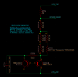
My suggested technique for maximizing ADC integrated in MCUs is oversampling, to shave pennies and producing better equipment at same cost for the masses (in the hope that some become techs too). The precision increases proportionally to the square root of the number of samples averaged, provided that there is enough noise with a frequency spectrum extending high enough for random toggling of +/-1 LSB or more of ADC. I just use some code to show numbers by RS232 in text terminal in PC to verify adequate toggling. The circuit of a simple temperature compensated noise generator is attached.
The averaging can be FIR (summing all samples over a period of time, giving one higher precision sample per summing interval) or one or two 1st order IIR LPF (result=result+(ADC-result)*coef) with coef chosen for enough attenuation at sampling freq.
Looking at the old HP schematics from year 2000 it's obvious that they were not taking fully advantage of current technologies, it would be SMD and with more digital and analog integration otherwise, but it is looking more like 1990s.
My suggested technique for maximizing ADC integrated in MCUs is oversampling, to shave pennies and producing better equipment at same cost for the masses (in the hope that some become techs too). The precision increases proportionally to the square root of the number of samples averaged, provided that there is enough noise with a frequency spectrum extending high enough for random toggling of +/-1 LSB or more of ADC. I just use some code to show numbers by RS232 in text terminal in PC to verify adequate toggling. The circuit of a simple temperature compensated noise generator is attached.
The averaging can be FIR (summing all samples over a period of time, giving one higher precision sample per summing interval) or one or two 1st order IIR LPF (result=result+(ADC-result)*coef) with coef chosen for enough attenuation at sampling freq.
Attachments
Last edited:
btw: Amazing ADCs, the AD7708/7718 seem intended for measuring equipment, and the others AD76xx/AD79xx for more general applications. But the R&D has been already done almost completely by AD, to the point of producing an ADC not requiring external scaling op-amps for most measurements, reflected in the price of course, so these chips will never find use in consumer equipment, where the techniques used are different. Oh, wait a minute, are we producing techs that cannot design consumer equipment? hehe
My suggested technique for maximizing ADC integrated in MCUs is oversampling, to shave pennies and producing better equipment at same cost for the masses (in the hope that some become techs too). The precision increases proportionally to the square root of the number of samples averaged, provided that there is enough noise with a frequency spectrum extending high enough for random toggling of +/-1 LSB or more of ADC. I just use some code to show numbers by RS232 in text terminal in PC to verify adequate toggling. The circuit of a simple temperature compensated noise generator is attached.
The averaging can be FIR (summing all samples over a period of time, giving one higher precision sample per summing interval) or one or two 1st order IIR LPF (result=result+(ADC-result)*coef) with coef chosen for enough attenuation at sampling freq.
I will hang onto this, and experiment with this at another stage. I've seen this
technique used in this application note, I think for DC application this will work well, but at higher sampling rates this technique wont work as the injected noise will introduce all kinds of issues. thanks for the tip!
http://www.atmel.com/images/doc8003.pdf
External ADC is all ok. Another version with built in ADC can be discussed later.
Reactance, I can help you with the hardware (mosfets part) if you a bit confused with it. I'm a pro, don't worry.
if you place irfp250n in your list, it is better to use 4 instead of 2 for better breakdown margin.
Reactance, I can help you with the hardware (mosfets part) if you a bit confused with it. I'm a pro, don't worry.
if you place irfp250n in your list, it is better to use 4 instead of 2 for better breakdown margin.
I bought (this) DC electronic load to test my power supplies. It's rated for 80 volts, 30 amps, 300 watts maximum. When I took it apart and looked inside, the majority of the design and construction effort was focused upon (i) routing and distribution of very high current paths (at extremely low voltage drop), (ii) heatsinking, and (iii) thermally controlled fans. Lots and lots of fans. When the unit is in operation, it seems to have four discrete fan speeds: off, low, medium, and high; rather than a continuously varying speed. But I could be mistaken; I was merely listening to the amplitude and the pitch of the collection of spinning fans.
The ADCs and DACs and input controls and output displays, seemed not to be where these designers spent the bulk of their effort and construction budget.
The ADCs and DACs and input controls and output displays, seemed not to be where these designers spent the bulk of their effort and construction budget.
- Status
- This old topic is closed. If you want to reopen this topic, contact a moderator using the "Report Post" button.
- Home
- Amplifiers
- Power Supplies
- DC Electronic Load