Thanks for the replies, everybody. I'm learning (I think)... 
I suppose AC heating would be the simplest way to go, if it can be done so that there's no hum audible at the speakers. So the trick is to use a separate filament transformer for each DHT? For 5V, closest I could find is the Hammond 166L5, 5VCT @ 2A, for about $20 each ($80 for the four tubes). The next closest is Hammond 166J5, 5VCT @ 1A. I guess I'd have to use the 2A version and burn off some excess volts. I've done that with small value wirewound resistors, paralleled up. Seems wasteful, but it looks like nobody makes a 5VCT @ 1.25A transformer available off the shelf.
Anybody have a recommendation for a reasonably safe way to match the phasing of the 5V secondaries?
On the other hand, a separate CCS for each filament would be do-able. I didn't know about Antek. Very handy source for trannies! So I would need to first regulate the voltage to 5VDC, then regulate the current to 1.25A per tube?
Forgot to mention... Cathode bias.
There will always be some hum left at the speaker. Depending on the sensitivity of your speakers you may be able to hear it... There are various tricks for dealing with it. Run a search on "humdinger" and you'll find.
George (tubelab) mentions on his website that he converted to DC heaters on his DHT as the AC from the filament was causing IMD products resulting in a 'fuzzy' sound.
With DC heating you have to select between two options: constant current OR constant voltage. You only regulate one of the two variables. The resistance of the filament will determine the current (for constant voltage) or voltage (for constant current) according to Ohm's law.
For constant voltage operation, you design the regulator to deliver 5.0 V. The regulator needs to be capable of supplying at least 1.5 A as some types of 300B's (JJ for example) draws 1.4 A of filament current. For constant voltage operation only the voltage is regulated, but the current is limited (the regulator can only supply so much).
For constant current, you design the regulator to supply the rated filament current (1.2 A for the original WE 300B I think; 1.4 A for JJ 300B, etc.) You need to make sure the regulator has enough voltage headroom (also known as compliance voltage) or it won't be able to supply the needed current. I.e. you need to make sure the output voltage of the regulator can reach 5.0 V - or slightly above under worst case operating conditions. For constant current operation, the current is controlled by the regulator but the voltage is limited (the regulator can only supply so much).
In my opinion, constant voltage is the easiest to approach by a beginner, which is one reason I have been tooting that horn in this thread. The 1.5 A current limit of the LM317 provides a nice soft-start or in-rush limiting so the filament doesn't get too stressed.
~Tom
I am running this circuit for 5 years now. Zero problems and the difference in sound is anything but subtle. It's huge. Must say I run my 300B's with fixed bias.
Tube filament supply
Tube filament supply
I am running this circuit for 5 years now. Zero problems and the difference in sound is anything but subtle. It's huge. Must say I run my 300B's with fixed bias.
Tube filament supply
What heater supply did you use before?
I find it humorous that they tout that the current source has high output impedance. While it is true that a current source has high output impedance, the impedance at the node where the current source connects to the filament is quite low (about 4 ohms for a 300B) as it's "looking" through the filament to ground.
It sounds like their circuit is basically a current source where the compliance voltage is set to the required filament voltage (5.0 V for a 300B).
~Tom
DC with a standard 5V regulator (L78S05).
have you checked http://www.tentlabs.com/Products/Tubeamp/Tubefilament/assets/Heatingmethods.pdf ?
have you checked http://www.tentlabs.com/Products/Tubeamp/Tubefilament/assets/Heatingmethods.pdf ?
phasing ac filaments
I phased the two trannies my measuring the hum at output. Reverse one pair to get lowest reading. With 300b filaments, the wiring dress is very important, as any noise the filament wire pick up will be audible. DC heating seems to be more forgiving in this regard, but care still must be taken. Make sure all wires are tightly twisted (I use a drill to twist to 5-6 turns per inch). The hammond transformers you mentioned are what I use. I placed a 50 ohm, 10 watt resistor in series with the primaries of the pair to get voltage to about 5.1 volts. I had tried previously using one ct transformer to power both 300b's, but could never get the hum levels down below 6-7mv. I used dc on them for a while, but actually went back to ac because of its simplicity. My speakers are quite sensitive (GPA 604's), but the hum isn't audible unless you get fairly close and listen for it specifically. My single ended 300b amps use dc, simply filtered via lclc, and are dead quiet (.2-.3mv).
I phased the two trannies my measuring the hum at output. Reverse one pair to get lowest reading. With 300b filaments, the wiring dress is very important, as any noise the filament wire pick up will be audible. DC heating seems to be more forgiving in this regard, but care still must be taken. Make sure all wires are tightly twisted (I use a drill to twist to 5-6 turns per inch). The hammond transformers you mentioned are what I use. I placed a 50 ohm, 10 watt resistor in series with the primaries of the pair to get voltage to about 5.1 volts. I had tried previously using one ct transformer to power both 300b's, but could never get the hum levels down below 6-7mv. I used dc on them for a while, but actually went back to ac because of its simplicity. My speakers are quite sensitive (GPA 604's), but the hum isn't audible unless you get fairly close and listen for it specifically. My single ended 300b amps use dc, simply filtered via lclc, and are dead quiet (.2-.3mv).
DC with a standard 5V regulator (L78S05).
have you checked http://www.tentlabs.com/Products/Tubeamp/Tubefilament/assets/Heatingmethods.pdf ?
They do make a good point. The potential difference across the heater will cause the cathode current at one end of the heater to be different than that at the other. This will set up an AC current (audio signal) running through the cathode/heater. With AC ground (power supply) at one end of the cathode and a low-impedance DC heater supply, the induced AC current will split between the AC ground (supply ground) and the DC heater supply. I.e. part of the induced current will run through the heater supply regulator. Having a heater supply with a high output impedance (current source) will cause this induced current to prefer the route through the AC ground to the main B+ power supply. As the current induced in the heater is supplied by the B+ supply, it should be returned through the B+ supply ground (AC ground). Thus, operating with a current source as the heater supply, should improve performance.
Cool!
I think my lab supply has a current source mode, actually. That would make it really easy for me to try this out. Almost too easy...
I'll report back with results.~Tom
Zo.... I have my trusty ol' Sorensen QRD 40-2 supplying 5.0 V to my 300B driven by a 6SL7 through a source follower (think Tubelab SE). By twisting the current limit knob I can now try constant current vs constant voltage.
I'm not hearing any difference between the two. None. Nada. Zilch!
The THD measures the same between the two configurations - in fact the 2nd and 3rd harmonic are slightly (0.3 dB) lower with constant voltage than constant current. With a square wave input, the first 10 harmonics are within +/- 0.2 dB on the two setups. The THD (sine input) was measured at 1.0 W into 8 ohm. The square wave test was done with the fundamental (1 kHz) at 0 dBV(RMS) on the output.
~Tom
I'm not hearing any difference between the two. None. Nada. Zilch!
I suspected this would be the answer in any objective test
The true benefit of CCS filament supply is IMHO in more controlled warm-up of filaments and in generally keeping them in safe(r) operating area.
Zo.... I have my trusty ol' Sorensen QRD 40-2 supplying 5.0 V to my 300B driven by a 6SL7 through a source follower (think Tubelab SE). By twisting the current limit knob I can now try constant current vs constant voltage.
I'm not hearing any difference between the two. None. Nada. Zilch!
The THD measures the same between the two configurations - in fact the 2nd and 3rd harmonic are slightly (0.3 dB) lower with constant voltage than constant current. With a square wave input, the first 10 harmonics are within +/- 0.2 dB on the two setups. The THD (sine input) was measured at 1.0 W into 8 ohm. The square wave test was done with the fundamental (1 kHz) at 0 dBV(RMS) on the output.
~Tom
Your Sorenson bench supply probably is not representative of a high impedance filament supply. What is the AC impedance of the output in current mode over the audio band?
Anyway, I doubt difference would always be audible in every amp with every different cathode bias scheme, etc. since the filament is essentially only a few ohms impedance in series with the cathode.
Michael
If a voltage regulator works for you, that's great news; it's a lot easier and cheaper than a CCS, VCCS, gyrator, etc.
Last edited:
I don't understand how a CCS vs a CVS could possibly be different.
One the filament heats up to steady state, the resistance should be constant. Ohm's law is simple.
If I have a constant resistance and a constant voltage, then current must also be constant and so on.
Really, the only parameter is which you prefer to control, voltage or current, but the end result must be the same.
Can someone educate me as to why a voltage differential over the length of the filament makes and audible hum? Every stretch of wire with resistance, every resistor or any other component has resistance and therefore a voltage gradient. You cannot avoid this.
How does an AC voltage gradient create noise, beyond what might be there due to the AC itself? It seems that the voltage gradient shouldn't be the problem, it is whether AC is noisier than DC, and if regulation, in the form of current or voltage regulation helps by reducing any DC ripple to nothing and by providing a high source impedance so signal noise isn't injected back into the power supply.
A constant voltage source has high output impedance, a constant voltage source has low output impedance.
IF TentLabs' claim of an induced AC current in the filament is correct, then a filament powered by a current source would route the AC current to ground rather than into the output of the filament regulator. With a voltage source, the induced AC current would split between the ground node (one end of the filament) and the filament regulator output impedance (other end of filament).
However, having mulled over this for a bit, I'm not sure TentLabs' claim is correct. As far as I understand it, a directly heated triode works as follows: A cathode/heater is heated to the point where electrons are emitted by the cathode. These electrons form a space-charge cloud around the cathode. The anode pulls electrons from the space-charge cloud. The flow of electrons may be modulated by the grid-to-cathode voltage. So far so good... I think where the TentLabs' argument falls apart is when it comes to setting up an AC current in the cathode/heater by the difference in Vgk across the cathode. I don't think that claim is true. Once an electron has been emitted by the cathode it joins the space-charge cloud where it is indistinguishable from any other electron. As the electrons are have the same charge, they should distribute evenly around the cathode as they repel each other. It may be that the Vgk gradient across the heater will cause a gradient in the current flow between the space-charge cloud and the anode, but that gradient should be completely decoupled from any current flow in the cathode. At least on a small scale (we're talking a Vgk gradient of 5 V versus Vak of 400 V) the currents should be decoupled. The cathode emissivity is constant across the length of the filament as the emission is driven by temperature.
As the emissivity is constant across the filament and the current gradient of the space-charge cloud is decoupled from the cathode current I think TentLabs' argument is fundamentally flawed.
That's my current thinking anyway...
~Tom
I may be doing a very poor job of explaining this, but basically, in a dht you have (in the case of 300b) 5 volts difference in bias at one end of filament versus the other, which with ac is constantly changing. Depend on how accurately the filament is centered, the bias fluctuates slightly with each directional change, inducing hum. humpots, ct transformers, etc all function to locate the electrical center of the filament, and minimize the hum. With dc, since there is no change, this problem isn't there. There will be a difference in bias current at opposing ends of the filament, and people have come up with various schemes to deal with this, if they felt it to be important. In a conventional ac set up, where the dc and signal ground is supplied via a center tapped hum pot, the transformer secondary, and the leads to the tube are floating at a relatively high impedance and act like an antenna for noise, which is why precautions need to be taken. With most dc arrangements, a final filter cap gives a fairly low impedance to noise in the 60-120 hz range, so other than the noise caused by producing the dc itself (rectifier hash, etc.) dc heating is a little easier to keep quiet.
Jim: Our posts may have crossed, but I don't think there is a difference in bias current across the filament due to the emission driven by temperature and not Vgk -- see above.
But as far as AC vs DC, it's clear that DC is the way to go. AC heating is essentially like applying a 5 V 50/60 Hz signal on the cathode of an indirectly heated tube. The gain from that node to the output is not great, but it's enough to cause the AC to get through to the output.
In addition, any noise on the heater voltage will couple capacitively to the grid and anode -- but that applies both to DC and AC.
A well-regulated DC will be very quiet. That's the way to go.
~Tom
Wow, this turned into quite an educational thread for me. To distill it down, does everyone pretty much agree with the following?
1) For DHTs, DC filament supplies will reduce hum and possibility of AC hum modulating audio signal.
2) If AC filament supply is used, an individual transformer should be used for each, individual DHT. For some reason, this reduces hum down to very manageable levels.
______________________________
Then it comes down to a question of cost. Let's say I'm thinking of making something crazy, like a push-pull, parallel 2A3 amp. For a pair of monoblocks, this will require eight 2.5VCT 2.5A transformers, like Hammond 166L2. These cost about $22 each (US), so for stereo that will cost $196 plus s/h, so let's say an even $200. Then add the hum-balance pots. (Would these pots need to be wirewound types)?
If we use 2.5VDC 10A for each quad of 2A3's, then we'll need two transformers of something like 10VCT rated at 10A+. Those all seem to cost about $65 each, and we'll need to purchase the needed diodes, IC's, resistors, capacitors, heatsinks, etc.
It looks like if you can use a single transformer for each channel, then DC is less expensive. Is it OK to use a single (unregulated) 6VDC supply to supply a separate LM350 for each of the four 2A3's?
What circuitry is necessary to distibute the load evenly between the four LM350s needed for each channel's 2A3s? Something based on this?:
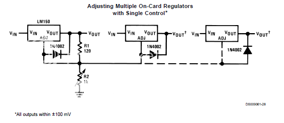
Copied from the National Semiconductor datasheet for LM350.
In the above, R1 and R2 would both be the same value for 2.5VDC out. Minimum load needs to be 10A (very convenient for a quartet of 2A3s, as each draws 2.5A). The picture seems to indicate that the R1/R2 voltage divider sets the output for the entire chain. I don't know how or why that works, but I'll go with it. Does that look right?
--
1) For DHTs, DC filament supplies will reduce hum and possibility of AC hum modulating audio signal.
2) If AC filament supply is used, an individual transformer should be used for each, individual DHT. For some reason, this reduces hum down to very manageable levels.
______________________________
Then it comes down to a question of cost. Let's say I'm thinking of making something crazy, like a push-pull, parallel 2A3 amp. For a pair of monoblocks, this will require eight 2.5VCT 2.5A transformers, like Hammond 166L2. These cost about $22 each (US), so for stereo that will cost $196 plus s/h, so let's say an even $200. Then add the hum-balance pots. (Would these pots need to be wirewound types)?
If we use 2.5VDC 10A for each quad of 2A3's, then we'll need two transformers of something like 10VCT rated at 10A+. Those all seem to cost about $65 each, and we'll need to purchase the needed diodes, IC's, resistors, capacitors, heatsinks, etc.
It looks like if you can use a single transformer for each channel, then DC is less expensive. Is it OK to use a single (unregulated) 6VDC supply to supply a separate LM350 for each of the four 2A3's?
What circuitry is necessary to distibute the load evenly between the four LM350s needed for each channel's 2A3s? Something based on this?:
Copied from the National Semiconductor datasheet for LM350.
In the above, R1 and R2 would both be the same value for 2.5VDC out. Minimum load needs to be 10A (very convenient for a quartet of 2A3s, as each draws 2.5A). The picture seems to indicate that the R1/R2 voltage divider sets the output for the entire chain. I don't know how or why that works, but I'll go with it. Does that look right?
--
Last edited:
1) For DHTs, DC filament supplies will reduce hum and possibility of AC hum modulating audio signal.
2) If AC filament supply is used, an individual transformer should be used for each, individual DHT.
Agreed.
For some reason, this reduces hum down to very manageable levels.
If the filament winding has a center tap, ground this tap. This theoretically cut the hum by 6 dB (= half). Aside from that, there's no magic reason why it works. The filament windings may reside on the same transformer core, but must be separate windings as they carry different cathode current to ground. Remember that in a DHT, the filament is the cathode.
Then add the hum-balance pots. (Would these pots need to be wirewound types)?
Very likely. It depends on how much power you'll dissipate in the pot.
If we use 2.5VDC 10A for each quad of 2A3's, then we'll need two transformers of something like 10VCT rated at 10A+.
For 2.5 V DC you should be able to get away with a 5 V transformer (do the math, but I'm quite sure). I'd look at what Antek has to offer. $65/each sounds expensive...
It looks like if you can use a single transformer for each channel, then DC is less expensive. Is it OK to use a single (unregulated) 6VDC supply to supply a separate LM350 for each of the four 2A3's?
I think one LM350 per 2A3 would be a sleek and fairly inexpensive solution. Figure you'll need at least 2.5 V across the LM350. So the input voltage should be higher than 5.0 V at all times, i.e. make sure the ripple voltage doesn't cause the input voltage to the LM350 to drop below 5.0 V.
As you stated earlier, pick R1 = R2 to get 2.5 V out. Pick the R1, R2 in the range of 120~250 Ohm. With +/- 1 % tolerance resistors, there's really no need for a voltage adjustment as the output voltage will be within 2.5 V +/- 5 %. If you insist on having some level of adjustability, I suggest limiting the range of the pot by using a small pot with a series resistor. Say, R1 = 220 Ohm. R2 = 100 Ohm pot + 180 Ohm resistor. That'll give you a total range of 2.27 V ~ 2.84 V
~Tom
Thanks for your reply.
I checked out the Antek site. They are way less expensive than Hammond. Unfortunately, they don't have a 6V xfmr rated any higher than 50VA (4.2A).
They do have a 9V 100VA xfmr (5.6A), for $18 each.
Their xfmrs have dual secondaries, so I'm not sure exactly how to interpret their ratings. Is that 9V @ 5.6 per secondary winding? So if you parallel the two windings, do you get 9V @ 11.2A? The windings' phase needs to be matched, of course.
I also found a different xfmr, 6.3VCT @ 10A. Do I need more than a 10A rating because of the power dissipated by the LM350s?
--
For 2.5 V DC you should be able to get away with a 5 V transformer (do the math, but I'm quite sure). I'd look at what Antek has to offer. $65/each sounds expensive...
I checked out the Antek site. They are way less expensive than Hammond. Unfortunately, they don't have a 6V xfmr rated any higher than 50VA (4.2A).
They do have a 9V 100VA xfmr (5.6A), for $18 each.
Their xfmrs have dual secondaries, so I'm not sure exactly how to interpret their ratings. Is that 9V @ 5.6 per secondary winding? So if you parallel the two windings, do you get 9V @ 11.2A? The windings' phase needs to be matched, of course.
I also found a different xfmr, 6.3VCT @ 10A. Do I need more than a 10A rating because of the power dissipated by the LM350s?
--
Thinking about it, I think I can answer one question for myself...
9V * 11.2A = 100.8VA
So the two 5.6A secondaries together make 11.2A, and we get the 100VA rating. Correct?
They do have a 9V 100VA xfmr (5.6A), for $18 each.
Their xfmrs have dual secondaries, so I'm not sure exactly how to interpret their ratings. Is that 9V @ 5.6 per secondary winding? So if you parallel the two windings, do you get 9V @ 11.2A? The windings' phase needs to be matched, of course.
9V * 11.2A = 100.8VA
So the two 5.6A secondaries together make 11.2A, and we get the 100VA rating. Correct?
- Status
- This old topic is closed. If you want to reopen this topic, contact a moderator using the "Report Post" button.
- Home
- Amplifiers
- Tubes / Valves
- DC Current-Regulated 300B filaments?