Hey Anyone,
I want to build a DC coupled amp. It would be a SE amp using a 6GK5 to drive a parallel pair of 6P15p outputs. (If this is even possible that is) The idea came from the fact that the 6GK5 runs well in the 135 to 150 volt range. Which is about the right voltage for 6P15P grid 2. My question is would applying 150 volts DC to grid 1 be possible? And if that can be done would it make it unnecessary to apply voltage to grid 2? Or would the DC have to be applied to both grid 1 & 2? I'm assuming there would need to be a grid stopper in place to limit current? I have all the parts to build this amp. And will only DC couple it if it would possible. Of course I could build it without the cap first, assuming it wouldn't damage the tubes. Any help would be much appreciated.
Kevin
It is possible to apply 150V to g1 of a 6P15P. The valve probably won't survive such rough treatment, though. g1 and g2 are not the same thing so you can't swap their voltages around. I think you need to do some more reading about how pentodes work.
Some valves can have g2 drive. I don't know if that is one of them. In some cases (very beefy valves) a feed for g1 (via a resistor to limit current) can also be done. Generally this is only for valves designed for Class C or AB2, as they can cope with g1 grid current.
Some valves can have g2 drive. I don't know if that is one of them. In some cases (very beefy valves) a feed for g1 (via a resistor to limit current) can also be done. Generally this is only for valves designed for Class C or AB2, as they can cope with g1 grid current.
Thanks DF96,
So driving grid 2 with the AC input is possible? That thought had occurred to me. It would be simple enough to try. If it doesn't work I could just add a coupling cap to grid 1. I could also try DC coupled to grid 2 withAC coupling to gird 1? Or two inputs to the tube might really muck things up?
The thing about being an amateur is you don't know what won't work.
Kevin
Probably not going to work, see Tubelab's comment re EL84 (which is similar to the 6P15P other than the internally connected G3)...
Screen Drive EL84
Screen Drive EL84
jazbo,
Thanks for the thread. Quoting Tubelab,
Kevin
Thanks for the thread. Quoting Tubelab,
Maximum screen grid voltage on 6P15p is 150 volts. I know from experience that 6P15P is verysensitive much more than EL84. Also, Anatoliy tells me that on 6P15P grid2 is denser than EL84. So it might just work. Its worth a try.You want to look for the lowest maximum screen grid voltage rating that you can find. This implies good screen sensitivity.
Kevin
Last edited:
The big advantage of screen drive is in push-pull, where you can run very low quiescent current with low distortion. In SE, you need an extra stage (cathode follower to supply grid current) plus more gain. But it can be done - see: Tube-Town Germany - Hot Stuff Cool Sounds
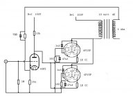
Such a scheme to stabilize DC operating point is worth investigating. Mullard 3-3 also uses DC feedback: http://vintageradio.me.uk/amplifier/mullard33_2.jpg
Such a scheme to stabilize DC operating point is worth investigating. Mullard 3-3 also uses DC feedback: http://vintageradio.me.uk/amplifier/mullard33_2.jpg
Probably not going to work, see Tubelab's comment re EL84 (which is similar to the 6P15P other than the internally connected G3)...
Screen Drive EL84
It is similar, but not exact: 6P15P has denser G2, so G2 drive will work better than with EL84.
Here I have some data, including curves from "Not for public" book:
www.wavebourn.com • View topic - 6p15p data ?????? 6?15?
Maximum screen grid voltage on 6P15p is 150 volts.
The data sheet says max. Ug2 is 330 volts. 150 volts is typical operating point.
http://www.mif.pg.gda.pl/homepages/frank/sheets/113/6/6P15P.pdf
jeff
- Status
- This old topic is closed. If you want to reopen this topic, contact a moderator using the "Report Post" button.
- Home
- Amplifiers
- Tubes / Valves
- DC coupled 6P15P