Hi:
Is there a DIY amplifier with PCBs available that would easily lend itself to being modified for operation to DC?
This would be used as a GP lab. amplifier, for purposes such as motor servo drive, exciting ferrite & iron core transformers, charge/discharge battery characterization (without the complications caused by the often pulsed behavior of existing hobby chargers), etc.
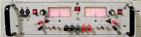
Something like a Kepco BOP. (That has a current loop too, which shouldn't be difficult to add.)
Small signal BW to 100kHz would be ideal, but full power BW could be 20kHz. Power of 50 or more watts into 4-8 ohms...
Thanks for input!
Is there a DIY amplifier with PCBs available that would easily lend itself to being modified for operation to DC?
This would be used as a GP lab. amplifier, for purposes such as motor servo drive, exciting ferrite & iron core transformers, charge/discharge battery characterization (without the complications caused by the often pulsed behavior of existing hobby chargers), etc.
Something like a Kepco BOP. (That has a current loop too, which shouldn't be difficult to add.)
Small signal BW to 100kHz would be ideal, but full power BW could be 20kHz. Power of 50 or more watts into 4-8 ohms...
Thanks for input!
Why not a NAP-140 clone? It's easy to get a kit from Ebay.
You will have to remove two caps. Of course the input cap, but also the one in the feedback divider. This will cause some DC issues of course. If the DC offset normally is below some 30mV it will now be hard to make the offset lower than 500mV, but tht's perhaps acceptable.
But the introduction of a trim pot may lower the offset further.
And if you glue the transistors of the LTP together I think it will be quite stable.
IMO a design based around a HV opamp like the ADA4700-1 with a power buffer would be more suited to lab supply purposes, but I don't think there's such a board kicking around that you can buy. Although it would be relatively simple to design. There are certainly some helper signal processing functions that you would want to design into such a device along with the power supply core.
And you'll get a pretty good audio amplifierIMO a design based around a HV opamp like the ADA4700-1 with a power buffer would be more suited to lab supply purpose.
I'll have a look at the NAP-140.
Perhaps it does make sense to use an HV op-amp with a power booster, rather than roll my own, since I've only an elementary understanding of the workings of all the inner parts of an op-amp.
And, offset is something I love to hate in a DC-coupled amp, so I'll want to have as little as possible to start with, incl. low ofs. drift.
What is the cause of input offset anyway? Is it simply the mismatch btw. the input transistors? Is the input offset current due to mismatch of beta, and the input offset voltage a result of mismatch of Vbe?
I built a class-D lab amp for voice-coil servo actuation years ago using an Apex chip. That had a current and voltage loop, and all sorts of jumpers to change configurations. With the current loop inside, it only worked to 10kHz. But it could output 7A and 500W.
Now there are 4 of them sitting in my lab at work with nothing do do since the variable valve timing project ended, but of course I can't have them :-( .
I guess I should review AoE again too, which has a lab amp. example.
Thanks for input!
KEPCO BOP is only good to 20kHz. I was able to pick one up quite inexpensively, they now go for~$600.
Nelson Pass F5 will operate from DC to around 1.5MHz but only 20W, the Turbo version will do 100W. You dont have to bias it all the way into Class-A.
TI has some "new-ish" power IC chips, check with their sales force to see if they have any development boards. They are in the section for table shakers, laser diode pulsers etc.
Attachments
Last edited:
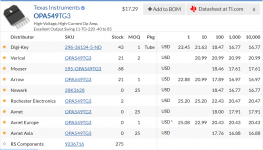
OPA549 will deliver 43WRMS into 8 ohms and double that into 4 ohms. One chip, a few resistors, and a power supply. Done. Datasheet below.
Need more power? Connect two OPA549s in bridged operation and get 2X output power. Easy.
_
Need more power? Connect two OPA549s in bridged operation and get 2X output power. Easy.
_
Attachments
All my amplifier have more than 20kHz full power BW: Anistardi's Blog | Elektronika dan Pemograman
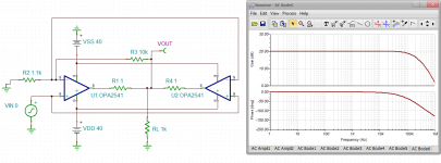
Parallel OPA2541 -- JFET input
But that is not full power, or is it?
Funny. At the beginning of the year I started the very same project for myself. Even the target specs were the same.
Very soon I realized, that I need two Amplifiers.
(1) A high bandwith version (100-200kHz) with less current capability and less protection circuitry but sufficiently high output voltage swing.
(2) A low bandwidth (proably max 20kHz) version that is more targeted to powersupply and current source/sink applications. More sophisticated protections are mandatory.
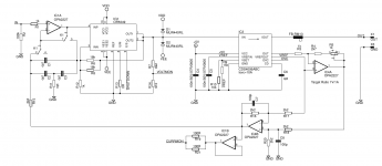
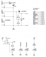
Because it is the easier one I started with option (2) and came up with the circuit below, which is a pretty straight OPA549 approach. Ive implemented a VCVS-mode and a VCCS-mode (voltage controlled current source) which can be chosen by a front panel switch. voltage gain is fixed 20dB. Output-voltage- and output-current can be monitored via two BNC-outs.
Circuit is not fully tested and the current control loop parameters are not designed yet. Wanted to construct the chassis first.
Currently I am struggling with choosing an appropriate power supply. I narrowed down my choices to either
(a) a 300VA 2x18V toroidal transformer with oversized rectifiers, caps and so on [problem of unregulated rails, load dependency and less output voltage swing becaus of max 27V for the OPA549]
or
(b) two 240W 24V/10A Meanwell smps supplys conncted in series [better output voltage swing and more current capability but potential issues with additional EMI in the lab]
In the nex circuit rev. I intend to skip the current transducer and go for a good oldfashioned shunt in the lowside of the output connectors.
Comments welcome!
BTW check this out:
Product overview - Dr. Hubert
Very soon I realized, that I need two Amplifiers.
(1) A high bandwith version (100-200kHz) with less current capability and less protection circuitry but sufficiently high output voltage swing.
(2) A low bandwidth (proably max 20kHz) version that is more targeted to powersupply and current source/sink applications. More sophisticated protections are mandatory.
Because it is the easier one I started with option (2) and came up with the circuit below, which is a pretty straight OPA549 approach. Ive implemented a VCVS-mode and a VCCS-mode (voltage controlled current source) which can be chosen by a front panel switch. voltage gain is fixed 20dB. Output-voltage- and output-current can be monitored via two BNC-outs.
Circuit is not fully tested and the current control loop parameters are not designed yet. Wanted to construct the chassis first.
Currently I am struggling with choosing an appropriate power supply. I narrowed down my choices to either
(a) a 300VA 2x18V toroidal transformer with oversized rectifiers, caps and so on [problem of unregulated rails, load dependency and less output voltage swing becaus of max 27V for the OPA549]
or
(b) two 240W 24V/10A Meanwell smps supplys conncted in series [better output voltage swing and more current capability but potential issues with additional EMI in the lab]
In the nex circuit rev. I intend to skip the current transducer and go for a good oldfashioned shunt in the lowside of the output connectors.
Comments welcome!
BTW check this out:
Product overview - Dr. Hubert
Attachments
Parallel OPA2541 -- JFET input
Is it a good idea to parallel op-amps in this manner? Shouldn't U2 take it's feedback from it's own output?
Rather, you have the differential input voltage of U1 applied to U2. Wouldn't this only work assuming they are perfectly matched (which will seem to work fine in the sim.) but the actually built circuit will have mismatched open-loop gains for U1 vs. U2, so the output voltages of the two amps won't be balanced?
Very soon I realized, that I need two Amplifiers.
(1) A high bandwith version (100-200kHz) with less current capability and less protection circuitry but sufficiently high output voltage swing.
(2) A low bandwidth (proably max 20kHz) version that is more targeted to powersupply and current source/sink applications. More sophisticated protections are mandatory.
I'm heading toward a similar conclusion. Actually, I don't know if I really need any amplifier! I would just like one ;-)
Two things I actually do or plan to do is: 1. excite LC tank circuits to find resonance (for Tesla coil projects, and 60kHz WWVB receiver front end experiments); 2. make stable AC voltages from 10-250VAC or so, 20-20000Hz or so, to test/calibrate multimeters for AC voltage accuracy (low current).
I've got a growing a collection of digital and analog multimeters, plus a Keysight 34465A on the way which can be used as a cal. standard for all the lesser units. I can use one of my signal generators driving a step-up transformer for some of this. Such as a Edcor COM 400mW 50:10000ohm transformer.
Well that will only get me to about 50Vrms, so I need an amplifier!
Generally, having an amplifier on hand enables quickly trying experiments that otherwise would require building more circuitry before getting to the "it does something!" stage. Thus, it's a research work-flow expediting tool.
The other thing of interest is to create an AC voltage power supply for powering things for characterization, and where line voltage fluctuations make using a variac impossible to get the desired precision. Or otherwise just screwing around!
I've considered just buying a Behringer A500 or a cheap class-D and abusing it for purposes like this.
OTOH I've built up a collection of audio amp. transistors, so I'm ready to start building something DIY.
I should probably just buy one of the PCBs on the site and build up an audio amp. That could be used for well, audio, as well as all my AC calibration and some moderate power AC voltage power supply needs.
Then put together some simple breadboard versions of 1. a HF amp, capable of about 2W into 50R at up to 20MHz for the coil experiments (with enough power to light a neon in the field of the LC tank), and another higher-powered one with DC coupling if the day arrives that I start playing with motor (incl. PLL) controls again.
I suffer from project proliferitis, with the result being getting nothing done.
That's good to keep on hand, as at work we have sometimes the need for professional grade lab amps.
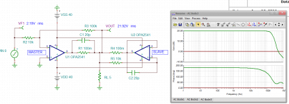
Master-Slave w OPA2541 -- from an old Burr Brown datasheet:
Yeah, that's more like what I'd expect would work.
Winfield's 100W DC-10MHz 1000V/us amplifier
Might be a bit advanced for your need, but well overdesigned for the application space! Also, if you're at either LLNL or Sandia, wave hi for me (I worked at LLNL for a couple years).")
If you have the money -- the Krohn Hite amplifier modules will do what you need, too.
Might be a bit advanced for your need, but well overdesigned for the application space! Also, if you're at either LLNL or Sandia, wave hi for me (I worked at LLNL for a couple years).
If you have the money -- the Krohn Hite amplifier modules will do what you need, too.
- Status
- This old topic is closed. If you want to reopen this topic, contact a moderator using the "Report Post" button.
- Home
- Amplifiers
- Solid State
- DC - 100kHz amplifier