Old discussion, but current problem for me
This is an old posting, but it helped me. Even negative results can be useful.
I was considering using the packaged Darlingtons, but I probably won't now. I did think about your problem, and I have a very strong hunch that the output devices are cross conducting destructively.
These old TIP142 and TIP147 Darlingtons are very slow compared to modern devices. Their turn off time is double the turn on time, so they can easily both be on when a high slew rate input drives them. Kaboom. Also, since they are slow, and the only negative feedback is from the output, the negative feedback is delayed and the drive overshoots, causing distortion. Designers use feedforward compensation and passive low pass filters on the input to avoid that. These Darlingtons are OK for servo amps and subwoofer amps, but not so great for higher frequency audio amps.
To make EF output stages faster, you need access to the base of the output transistor, which these packaged Darlingtons don't give. To see what I mean, take a look at the JBL T Circuit from 1966. The bases of upper and lower devices are tied together by resistors, not to the output line but to the opposite side. The result is stronger reverse drive and faster turn off. This fundamental technique has been known since the 60s.

There is a more subtle issue. I mentioned that the input signal should be low-passed. We know this from basic feedback control theory. Simply put, for feedback stability you need a passive low pass filter on the input that ensures that high frequencies are attenuated at frequencies well below the -3db point of the open loop gain. This requirement has been well known to engineers since the early 40s. The solution is so simple: precede the input with a passive RC filter of appropriate value.
A secondary issue is TIM, mainly caused by the slow output stage. The input stage is fast, and overdrives the output because negative feedback from the slow output transistors is delayed by their slow response. One result is audible, TIM. A second is that the output devices can be on simultaneously and can self destruct. Some designers work around this by returning some early feedback from the collectors of the drivers via small capacitors, so-called feedforward compensation. This helps TIM, but may not save the outputs.
As for other issues, namely bad thermal tracking of bias current with temperature and possible parasitic oscillations, the first has been covered. The second is dependent on random factors like physical layout and lead dress, as well as unstable circuitry design. I will just mention that I often see it on the driver collectors, and a crude but effective fix is 330pF caps to ground.
I've been toying with trying these Darlingtons in something new here, but I guess not. Thanks for negative results, very helpful. Keep pushing on your design, I know it can be solved. You'll value it more for the challenge.
This is an old posting, but it helped me. Even negative results can be useful.
I was considering using the packaged Darlingtons, but I probably won't now. I did think about your problem, and I have a very strong hunch that the output devices are cross conducting destructively.
These old TIP142 and TIP147 Darlingtons are very slow compared to modern devices. Their turn off time is double the turn on time, so they can easily both be on when a high slew rate input drives them. Kaboom. Also, since they are slow, and the only negative feedback is from the output, the negative feedback is delayed and the drive overshoots, causing distortion. Designers use feedforward compensation and passive low pass filters on the input to avoid that. These Darlingtons are OK for servo amps and subwoofer amps, but not so great for higher frequency audio amps.
To make EF output stages faster, you need access to the base of the output transistor, which these packaged Darlingtons don't give. To see what I mean, take a look at the JBL T Circuit from 1966. The bases of upper and lower devices are tied together by resistors, not to the output line but to the opposite side. The result is stronger reverse drive and faster turn off. This fundamental technique has been known since the 60s.
There is a more subtle issue. I mentioned that the input signal should be low-passed. We know this from basic feedback control theory. Simply put, for feedback stability you need a passive low pass filter on the input that ensures that high frequencies are attenuated at frequencies well below the -3db point of the open loop gain. This requirement has been well known to engineers since the early 40s. The solution is so simple: precede the input with a passive RC filter of appropriate value.
A secondary issue is TIM, mainly caused by the slow output stage. The input stage is fast, and overdrives the output because negative feedback from the slow output transistors is delayed by their slow response. One result is audible, TIM. A second is that the output devices can be on simultaneously and can self destruct. Some designers work around this by returning some early feedback from the collectors of the drivers via small capacitors, so-called feedforward compensation. This helps TIM, but may not save the outputs.
As for other issues, namely bad thermal tracking of bias current with temperature and possible parasitic oscillations, the first has been covered. The second is dependent on random factors like physical layout and lead dress, as well as unstable circuitry design. I will just mention that I often see it on the driver collectors, and a crude but effective fix is 330pF caps to ground.
I've been toying with trying these Darlingtons in something new here, but I guess not. Thanks for negative results, very helpful. Keep pushing on your design, I know it can be solved. You'll value it more for the challenge.
Last edited:
has anybody try to build a Darlington VSSA with
STD03N - Power Darlington 160V 15A (Master Part)
STD03P - Power Darlington -160V -15A (Master Part)
?
STD03N - Power Darlington 160V 15A (Master Part)
STD03P - Power Darlington -160V -15A (Master Part)
?
has anybody try to build a Darlington VSSA with
STD03N - Power Darlington 160V 15A (Master Part)
STD03P - Power Darlington -160V -15A (Master Part)
?
Not really at least not at the forum.
I do have some type of Sanken darlingtons from a damaged 5 channel amplifier, I will test those sometimes at winter.
Those are 3 pinned cheaper devices compare to the mentioned STD...

did you mean "open loop gain"?.......................
View attachment 571977
There is a more subtle issue. I mentioned that the input signal should be low-passed. We know this from basic feedback control theory. Simply put, for feedback stability you need a passive low pass filter on the input that ensures that high frequencies are attenuated at frequencies well below the -3db point of the open loop gain.
Most power amplifiers have an open loop gain that rolls off (f-3dB) down in the few dozen Hertz. It's very rare to see any that get up to 20kHz.
This requirement has been well known to engineers since the early 40s. The solution is so simple: precede the input with a passive RC filter of appropriate value. ...................
Last edited:
has anybody try to build a Darlington VSSA with
STD03N - Power Darlington 160V 15A (Master Part)
STD03P - Power Darlington -160V -15A (Master Part)
?
Hi
Here is these thread, same topology with HexFet. http://www.diyaudio.com/forums/solid-state/294834-cfh7-amp-50.html
I did not built these amp yet but I m planning so.
Somebody was kind to sent me a pair PC board freely to build and compared with the power darlington devices.
Several amp was built with great result based on the builder feedback. Reason I interested to check out these HexFet tend to sound different, not as soft or rounded at bass region like the LatFet.
My opinion based my own experience some others to like AKSA.
All do bot Fet has some advantage or disadvantage.
Several thread can be found the LatFet version were built successfully by hundreds of DIY-ers. It can NOT be bad!
To me the darlingtons gave great result, warm sound with good details and deep bass.
Please visit the HexFet site http://www.diyaudio.com/forums/solid-state/294834-cfh7-amp-50.html
The darlingtons you mentioned great devices but a bit pricy for my valet just to do some experimenting.
Of course feel free to modify the circuit and test it I would be interested on your experiment.
Just ordered parts for the simple circuit version with the minimum modification to see if it bring any stability to the Iq setting.
The other reason I know the sound of this amp before I do further modification to have the original as a comparison.
Of course, I have etched the PC boards also.
The other reason I know the sound of this amp before I do further modification to have the original as a comparison.
Of course, I have etched the PC boards also.
Attachments
Member
Joined 2009
Paid Member
Hey, great to see you are back at this circuit, you inspired me about this circuit many years ago.
I think the issue about the stability of Iq is going to be solved and you will have your dream amplifier !
The challenge with this symmetric VAS circuit is that there are two VAS devices instead of one VAS device with a current source load. Without the current source load (could be a bootstrap current source) the VAS current is not very well defined and can be less stable. The Vbe multiplier should provide a stable voltage to set bias of the output devices, but in fact the voltage across the Vbe multiplier does vary a bit with the VAS current - so if the VAS current varies then the voltage varies and the Iq will not be as stable as it could be. It may not be an issue at all but it is the very thing I investigated on my TGM5 amplifier. I found a simple solution, which was designed by Hagerman. See the document I have attached for the explanation. In my TGM5 I used solution shown in figure 2c, where I used a diode in place of Q11 of that diagram (Q11 is wired as a diode).
Attachments
Hi Gareth
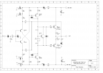
I think we went over that simplified option with the diode u mentioned, please take a look.
If I remember for some reason did not simulate well..
I think the layout I prepared I have the option to test that also. I printed out last year Ido not remember 100%.
I will try to test that in real life.
There is an error in the rail voltage I would not go over the 30V rail voltage with one pair of power Darlimgton. The 42V was for 2 pairs.
First I tested if the amplifier gained more stability after I will introduce the other modes we spoke about.
Same time I want to do A/B test also to hear if the sound gets changed by those modifications.
How you see that at the previous circuit that little amp put in shame sound wise some big dogs. I would love to keep that sound character if is possible.
The green parts only for the Toshiba power mosfets!
Greetings
Attachments
Member
Joined 2009
Paid Member
Looks good, but I didn’t simulate so I don’t know for sure. Some mystery is valuable! I am looking forward to see your posts as things progress.
If I didn’t send before, I can send you a pair of complementary Sanken output Darlington devices from my junk box when you are ready. 2SD2390 and 2SB1560.
If I didn’t send before, I can send you a pair of complementary Sanken output Darlington devices from my junk box when you are ready. 2SD2390 and 2SB1560.
Last edited:
- Status
- This old topic is closed. If you want to reopen this topic, contact a moderator using the "Report Post" button.
- Home
- Amplifiers
- Solid State
- Darlington VSSA