a 3rd way is synthesizing negative audio frequency impedance amplifier output with mixed feedback
An attenuator ahead of the power amp input with the foot resistor connected to a low value, current sensing, resistor inserted in the connection of the driver to ground does the trick.
Thiele has shown it applied on a valve amp in his papers on bass-reflex.
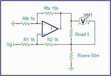
As it is positive feedback (R2 is bootstrapped by the voltage across Rsens) it is not universal and has to be tailored for a specific driver. It should not be found in usual commercial amps.
Here an example of a circuit which provides an output resistance of -2 Ohm.
.
Attachments
That will be around 7 Ohm for a unit with a nominal 8 Ohm impedance. This swamps all other resistances.
Surprising how many folks just don't consider this. I suppose you could weld a copper bar across the speaker leads and then you should not be able to move the cone.

I did say MOST amplifiers. Yours is one of the exceptions, which will give a noticeably different frequency response into some awkward speaker loads with electrostatic panels or ribbon tweeters. I have seen as low as 1 Ohm above 20 kHzPermit me to clarify things. One of my Blameless amplifiers, with conventional Miller compensation, gives about 0.02 Ohm at 10 kHz. That does not include an output inductor.
At low frequencies (10 Hz - 2 kHz) the output impedance is flat at 0.009 Ohms. This is low even compared with the internal wiring of a typical power amplifier.
This subject is dealt with in detail on p356-358 of the 6th edition of my book Audio Power Amplifier Design.
Here an example of a circuit which provides an output resistance of -2 Ohm.
.
-2 Ohm sounds a bit scary.
It might be worth using something like -0.03 Ohm, to cancel out the internal wiring resistance of the amplifier and the output inductor resistance. Tweak it right and you could wind up with virtually zero impedance at the output terminals.
I did say MOST amplifiers. Yours is one of the exceptions, which will give a noticeably different frequency response into some awkward speaker loads with electrostatic panels or ribbon tweeters.
Is there a "not" missing here?
Yours will be "different" because it doesn't do the low pass into low impedance loads that most amplifiers do. More accurate but it might sound bright as most speakers will have been voiced on amplifiers with output inductors.Is there a "not" missing here?
Once the amplifier really is "blameless", other steps in the chain have to be fixed too
'Blameless' amps are pretty straight forward. Is your amp unconditionally stable regarding RF without an output coil? If so, the design might be interesting. Any feedback around the output devices might be susceptible to RF ingress into the system. Generally speaking though, omit the output RF inductor at your own peril.
so lets consider an amp with 60000uF caps each of 10000uF x 6 per rail hence you would say that the amp with 60000uF will give better control over the cone than the one with 20000uF? I agree the fact at what power output level to be considered.
Forget the PSU factor now in terms of the DF being 10000 at 100Hz and I also agree that cables will eat away the DF but so in such scenarios does stiffer psu has control over the cone more? like If thats the case I would like to use atleast .1F per rail to get the best now here one more point comes into picture.
I have used a Van Den Hul Cs122 cable for the speakers hence driving a speaker with dual 8 inch woofer and guess the amp is ampcamp from pass 5Watt . It was powered using a laptop charger but still believe me the bass control was fantastic and it happened only when I used these cables then started to realize that the cable has very low resistance AWG 12 and hence contributing to the driver control now thinking to go with AWG 8 to get even lower resistance hence reducing the resistance of the wire.
It had hardly 4700uF of caps but my question was what made it to control the dual 8 inch driver with such control. Here psu is not at all stiff.... probably according to the previous posts it might be giving even more control than expected if we had stiff psu.
Here the cable resistance is reduced hence better control? or the cable has that magical factor to give that signature? ( I believe many start to argue in this magical case ).
Can you explain exactly what you are asking for? "Control" is very vague.so lets consider an amp with 60000uF caps each of 10000uF x 6 per rail hence you would say that the amp with 60000uF will give better control over the cone
Yamaha Subwoofers YST-SW80 and YST-SW150 (discontinued) had significant negative output impedance amps -- several ohms -- which increases motional feedback from the voice coil -- bascially a good thing for sound quality.... as long as you stay within excursion limits and unless the VC isn't stressed thermally.Do you know of a solid-state example of this? I'd be interested to see it.
When the low frequency signal becomes zero the cone should get from motion to stand still in no time extremely fast.
Agreed the fact of Fourier
Apparently not.
The bulk capacitance C is where all the current for the load comes from. The larger the capacitance, the more current
that can flow to the load before the supply voltage droops too much. I = C*dV/dt
If a full wave rectified supply (1/120 charging period) with 10,000uF capacitance has 3V ripple, then I = 3.6A.
Also the larger the supply capacitance, the lower the supply impedance feeding the output devices. Z=1/(2*Pi*f*C)
At 20 Hz, a 10,000uF power supply capacitor has an impedance of about 0.8 Ohms.
Bear in mind that the power supply capacitance is in series with the speaker (unless there is an output transformer).
Lets come to a practical calculation
Driver moving mass is 50gm so lets consider the amp is driver the woofer at 400Hz for the cuttoff so lets calculate the amount of energy required to get the cone to standstill. So lets take a driver with max displacement at the extreme considering 20mm peak to peak to stand still so in order to make such a moving mass 50gm to velocity zero.
So the Force required to stop the cone from its extreme motion to stand still.
F=ma where a = v* (dv)/(dx)
v= d/t 0.02meter /(1/400) = 8 mt/sec
a= 8 * (8-0)/0.02 = 3200m/sec^2
F= 0.05 x 3200
F= 150Nsec^2
in terms of Joules its 1470.99 Kilogram Joules meter
power required = Energy in Joules/ T in seconds
1470/0.0025 = 588396Watts of power required to do that job hence impractical to do get it to stand still in that time? so now the question is how it has to be calculated? or what is the optimum value?
588396Watts of power required to do that job hence impractical to do get it to stand still in that time? so now the question is how it has to be calculated? or what is the optimum value?
The amplifier only has to supply the "initial condition" displaced cone woofer current (at near zero output voltage) to damp the woofer.
Hence, very little power is actually needed, just a low source impedance.
Permit me to clarify things. One of my Blameless amplifiers, with conventional Miller compensation, gives about 0.02 Ohm at 10 kHz. That does not include an output inductor.
At low frequencies (10 Hz - 2 kHz) the output impedance is flat at 0.009 Ohms. This is low even compared with the internal wiring of a typical power amplifier.
This subject is dealt with in detail on p356-358 of the 6th edition of my book Audio Power Amplifier Design.
Mr. Self do you think it wold be better sounding if the amp you made had 0.02Ohm at 10KHz and 0.02Ohm at 10Hz? I bet it would
Lets come to a practical calculation
Driver moving mass is 50gm so lets consider the amp is driver the woofer at 400Hz for the cuttoff so lets calculate the amount of energy required to get the cone to standstill. So lets take a driver with max displacement at the extreme considering 20mm peak to peak to stand still so in order to make such a moving mass 50gm to velocity zero.
So the Force required to stop the cone from its extreme motion to stand still.
F=ma where a = v* (dv)/(dx)
v= d/t 0.02meter /(1/400) = 8 mt/sec
a= 8 * (8-0)/0.02 = 3200m/sec^2
F= 0.05 x 3200
F= 150Nsec^2
in terms of Joules its 1470.99 Kilogram Joules meter
power required = Energy in Joules/ T in seconds
1470/0.0025 = 588396Watts of power required to do that job hence impractical to do get it to stand still in that time? so now the question is how it has to be calculated? or what is the optimum value?
If you continue to ignore the Fourier theorem, you can spend hours generating nonsense calculations.
- Status
- This old topic is closed. If you want to reopen this topic, contact a moderator using the "Report Post" button.
- Home
- Amplifiers
- Solid State
- Damping factor of 100 at 10KHz?