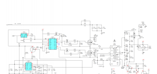
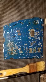
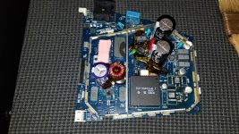
Hi there. I don't know if I'm posting this topic in the right place. The thing is, I have a Bose SoundDock 10 powered speaker with a damaged power supply. I have voltage in the high voltage part but the low voltage part only gives me 1 volt. I don't get voltage at the output. I have changed several components following the manufacturer's scheme but I still have no results. I changed the Q500 and Q501 mosfet transistors, which are the ones that supply power to the T502 transformer. I have also changed the U504 and U505 ICs and the C515 capacitor. The current reaches the transistor Q501 and the resistors that follow it, but I have no voltage on the secondary of the transformer, nor on the integrated circuits U504 and U505. At this point I am confused. Is it possible that the schmitt trigger U506 and the transistor Q509 are the cause of the current not going through this part? I put the photo of the part that I am testing and the schematics in case they are of any use. The power supply part number is: 322642-0010.
Thanks in advance.
Thanks in advance.
Attachments
Last edited:
It will be difficult because it has the ic's relabeled with their part number.
The main oscillator is a half bridge driver like several IR products. I would start by the test of the 15V supply. You will need an oscilloscope, an isoltation transformer to manage working with live voltages and a series lamp.
If you have those, measure the 15V supply to see if it is stady or has a sawtooth form. If steady, the IC controlling the MOSFET's is gone. If a sawtooth, the IC is supposed good but trying to start the bridge, but an alarm signal is found, usually an overcurrent because a shorted output (diodes, capacitors or the load itself).

Thank you very much for the information. I have replaced IC U504 and U505 but it still doesn't work. IC U504 only has 1 volt on any of its pins. What seems strange to me is that the Q501 mosfet has current but the Q500 does not. The Q501 mosfet receives approximately 650 volts. I have checked the resistors and they have the correct values and the diodes do not show a short circuit, but I have only checked them without unsoldering them. Is it possible that the transformer T502 is damaged?It will be difficult because it has the ic's relabeled with their part number.
The main oscillator is a half bridge driver like several IR products. I would start by the test of the 15V supply. You will need an oscilloscope, an isoltation transformer to manage working with live voltages and a series lamp.
If you have those, measure the 15V supply to see if it is stady or has a sawtooth form. If steady, the IC controlling the MOSFET's is gone. If a sawtooth, the IC is supposed good but trying to start the bridge, but an alarm signal is found, usually an overcurrent because a shorted output (diodes, capacitors or the load itself).
In my over 20 years of repairing and building SMPS never saw a failed transformer. This doesn't mean your may be the exception, but let it be the last responsible. In general terms, and in my experience, 45% of the problems are semiconductors, 45% in electrolytic capacitors, and the remaining 10% is shared between altered resistors, shorted diodes/load (exception is the output horizontal deflection transistor in VGA monitors failed because a failed HVT), overvoltage/crowbar circuits failed per se, or some other form of internal fault of the SMPS itself (under/over voltage lock out).
Try for instance, to remove the load to the SMPS but replacing the load by a resistor of the same estimated power drain as the load itself (dummy load in the jergon) and try again. But under no circumstance let the SMPS completely unloaded or shortcircuited nor remove the voltage sense circuitry usually implemented around a photocoupler and a voltage reference (TL431 or similar). It may be completely destroyed in milliseconds.
Try for instance, to remove the load to the SMPS but replacing the load by a resistor of the same estimated power drain as the load itself (dummy load in the jergon) and try again. But under no circumstance let the SMPS completely unloaded or shortcircuited nor remove the voltage sense circuitry usually implemented around a photocoupler and a voltage reference (TL431 or similar). It may be completely destroyed in milliseconds.
Thanks for the help. I have tried the power supply with the amplifier again but it still does not work. I haven't been able to connect a different load because I don't know what I could connect. On the other hand the output does not give me any voltage, with load and without load. The only part of the circuit that has voltage is from the AC input to transistor Q501 and the input transformer T502. But from that point I can't locate any part of the circuit with voltage. It's very frustrating since I've changed almost all the transistors on this part. Although I still have some components to check. I'm trying to find the FJV4104R transistor or equivalent, but I can't find it available anywhere. I have not been able to check ceramic capacitors because I do not have a capacitance meter. Can they be tested with a normal multimeter?In my over 20 years of repairing and building SMPS never saw a failed transformer. This doesn't mean your may be the exception, but let it be the last responsible. In general terms, and in my experience, 45% of the problems are semiconductors, 45% in electrolytic capacitors, and the remaining 10% is shared between altered resistors, shorted diodes/load (exception is the output horizontal deflection transistor in VGA monitors failed because a failed HVT), overvoltage/crowbar circuits failed per se, or some other form of internal fault of the SMPS itself (under/over voltage lock out).
Try for instance, to remove the load to the SMPS but replacing the load by a resistor of the same estimated power drain as the load itself (dummy load in the jergon) and try again. But under no circumstance let the SMPS completely unloaded or shortcircuited nor remove the voltage sense circuitry usually implemented around a photocoupler and a voltage reference (TL431 or similar). It may be completely destroyed in milliseconds.
Ceramic caps are difficult to fault. Ussualy semiconductors are the weakest part of the chain.
What is the voltage at pin#1, it seems to be some kind of output enable. In any case you can try remove R563 and force it low or high to see if oscillator starts. Use 100K tied to ground ot to 12V to prevent damage to the IC, 120uA will not destroy any CMOS input.
What is the voltage at pin#1, it seems to be some kind of output enable. In any case you can try remove R563 and force it low or high to see if oscillator starts. Use 100K tied to ground ot to 12V to prevent damage to the IC, 120uA will not destroy any CMOS input.
Last edited:
Do you mean the PIN1 of IC U504? The last time I checked it gave me less than 1 volt on each of its pins. But I would have to double check. So to do the test, would I just have to remove the R563 1.24K resistor and put a 100K resistor on it? With this test, would it be possible to know if the U506 is damaged?Ceramic caps are difficult to fault. Ussualy semiconductors are the weakest part of the chain.
What is the voltage at pin#1, it seems to be some kind of output enable. In any case you can try remove R563 and force it low or high to see if oscillator starts. Use 100K tied to ground ot to 12V to prevent damage to the IC, 120uA will not destroy any CMOS input.
Hello. Thanks for the help. I have done several tests and I have changed several components but the problem continues. I have changed IC U506, IC U503, bridge rectifier, and capacitor C509 because it was a dark color and gave me a strange reading. At this point, I don't know what to do. The problem is that I don't know how to isolate the error. After these changes the only thing I have detected is that the Q500 mosfet has around 300 volts and drops to 0 volts at the time of measurement. Another piece of information that I have to add is that when I started to repair this power supply, I put the multimeter between the input and the output of the rectifier bridge and this caused an explosion in the U505 transistor, which I have already changed. Could there be more components damaged by this short circuit? Could I connect an incandescent lamp with a capacitor in series between the negative of capacitor C409 and the output of the mosfet to check if the circuit oscillates?Ceramic caps are difficult to fault. Ussualy semiconductors are the weakest part of the chain.
What is the voltage at pin#1, it seems to be some kind of output enable. In any case you can try remove R563 and force it low or high to see if oscillator starts. Use 100K tied to ground ot to 12V to prevent damage to the IC, 120uA will not destroy any CMOS input.
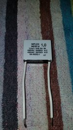
To test the oscillator, would this capacitor work? It's from a fan motor. But I don't know if it is of enough voltage.This is a good idea. Perhaps some resistors associated to it.
Attachments
Hi bro,Hi there. I don't know if I'm posting this topic in the right place. The thing is, I have a Bose SoundDock 10 powered speaker with a damaged power supply. I have voltage in the high voltage part but the low voltage part only gives me 1 volt. I don't get voltage at the output. I have changed several components following the manufacturer's scheme but I still have no results. I changed the Q500 and Q501 mosfet transistors, which are the ones that supply power to the T502 transformer. I have also changed the U504 and U505 ICs and the C515 capacitor. The current reaches the transistor Q501 and the resistors that follow it, but I have no voltage on the secondary of the transformer, nor on the integrated circuits U504 and U505. At this point I am confused. Is it possible that the schmitt trigger U506 and the transistor Q509 are the cause of the current not going through this part? I put the photo of the part that I am testing and the schematics in case they are of any use. The power supply part number is: 322642-0010.
Thanks in advance.
how about your SD10 now?
- Home
- Amplifiers
- Power Supplies
- Damaged Power Supply Bose SoundDock 10