This certainly has become your opportunity to play, hasn't it?
I would try disconnecting the ground on one input cable. Do not disconnect
the circuit's ground, or you will have trouble.

I'm starting to see where the loops may be.
This might be a longshot, and if all else fails... from your photo I can only see one bridge rectifier. Is there just one rectifier or are there two, one for each rail? If there is one, might try hooking it up with two like the power supply in the Aleph J build thread (same power supply as yours, basically). Sometimes a hum comes from just the one bridge for both rails. If you do have two, then please ignore this post. I hope breaking the ground on one of the input grounds solves it for you because that is the easiest.
Each signal wire is a twisted pair with its 0V connection.
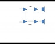
Studying the diagram there is clearly a loop in the centre.
I can see that disconnecting 0V from one of the RCA sockets would break this loop - How though would that channel work in isolation if the other channel was disconnected ?
Certainly during testing you might have only one input connected.
Studying the diagram there is clearly a loop in the centre.
I can see that disconnecting 0V from one of the RCA sockets would break this loop - How though would that channel work in isolation if the other channel was disconnected ?
Certainly during testing you might have only one input connected.
Attachments
Imo, assuming I am understanding, a not so great idea.
Removing the ground from one of the interconnects leaves it floating, in which case it is an invitation for vicious hum and noise, capable of trashing speakers and amplifiers - unless the grounded interconnect is connected first.
The problem would be worst case if the amp was on and not off.
I'd opt for the resistor to "ground" rather than the disconnected version, especially if this is sufficient.
The other issue is one of where the ground "reference" actually is.
There are different schemes for wiring an amplifier, they are not all equal in "groundedness".
_-_-
I have been successful using transformers with two separate secondary windings. Both windings are rectified separately. Then, voltages are joined at a single point, that is, 0V. The ripple is much lower compared to those with secondary with three leads. Much more if the current in both branches is very uneven. The crosstalk can be much better.
Modify the secondary side with three leads is easy. The results are very good. Of course, required another diode bridge for each channel.
regards
Modify the secondary side with three leads is easy. The results are very good. Of course, required another diode bridge for each channel.
regards
Diegomj,
I disagree.
I have tested a variety of dual winding dual rectifier into dual polarity supplies and compared that to many measurements of centre tapped single rectifier into dual polarity supplies.
I cannot tell them apart by noise or hum or buzz within the precision of my various measuring instruments. I have reported this a few times.
The only differences come when measuring the DC voltage, or when going to multi-channel.
DC voltage is lower for the dual rectifier.
Multi-channel has more problems with ground loop induced hum with single rectifier. This disappears with monoblock.
Diegomj,
I disagree.
I have tested a variety of dual winding dual rectifier into dual polarity supplies and compared that to many measurements of centre tapped single rectifier into dual polarity supplies.
I cannot tell them apart by noise or hum or buzz within the precision of my various measuring instruments. I have reported this a few times.
The only differences come when measuring the DC voltage, or when going to multi-channel.
DC voltage is lower for the dual rectifier.
Multi-channel has more problems with ground loop induced hum with single rectifier. This disappears with monoblock.
In the EI core transformers, generally, each half of secondary coil (when available center tap) has different electrical resistance because their winding lengths are different too. It is because of the fact that one half of the winding is wound around the other half of the winding.
When electrical currents by both branches are exactly the same, does not mean that the successive crests of rectified voltages are also the same (viewing the output waveform of each voltage branch). This necessarily produces additional undulations on the expected ripple due to the different heights of successive peaks. Each branch will have different regulatory capacity (due to the different internal resistance of semi-coils).
If the currents in both branches are very different, also will be the heights of successive peaks of voltage on the same branch.
One more thing: charging pulses through the main condensers, must circulate through the central tap (our 0 V reference). Nothing guarantees that these pulses are canceled between branches. Nothing guarantees that a branch does not interfere on the other branch.
The proposed option does not suffer from these problems. Using integrated diode bridges, the height difference between successive peaks is negligible (viewing the output waveform of each voltage branch). Much lower than the other option.
It can only exist differences between net voltages branches.
The charge pulses at the main capacitor does not return through the reference point (our 0 volts). They are different returns. The crosstalk is much higher than the other option. The point of 0 volts is much more quiet.
Even if two transformers with single secondary is used, the results are even more striking. The thermal interference is reduced (in the case of very different currents from both branches)
Regards
Last edited:
I'd opt for the resistor to "ground" rather than the disconnected version, especially if this is sufficient.
A reasonable approach. Maybe something like 22 ohms.

Does it know the words? (hummming... the old joke, you know...)
Unpower one channel.
See if it still hums.
Unpower the other channel/repower the first.
See if it still hums.
Be sure the PS caps a fully bled down before attempting this.
_-_-
Also, unbolt the power transformer, rotate it 90 deg in the horizontal axis (turn it on its side). See if that does anything.
Look at the residual on a scope, see what it looks like and what freq it is. (clues)
PPS. NP thinks I have a reasonable approach - must have me confused for someone else.
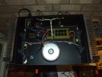
It doesn't look like that's the case. They appear to be in parallel with
filtered supply lines.
I suppose it is acceptable then
how about the AC mains tied to the wires from first two supply filter caps ?
btw, was it this amp that blew, and was repaired ?
Attachments

- Status
- This old topic is closed. If you want to reopen this topic, contact a moderator using the "Report Post" button.
- Home
- Amplifiers
- Pass Labs
- Dad's away so I can play