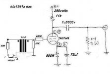
The cap needs to go on the bottom of the trans primary, kind of a parafeed arrangement, as a rough example. Take the cap off the input to the trans, flip it around and insert into the ground node of the primary and 50 ohm, + to trans primary low side and the neg to ground with the 50 ohm. Hope that makes sense.
Please explain Scott because when I read this it is just moving the cap from top to bottom of the primary and I guess that doesn't make a big difference

Or when I read it another way the DAC is not loaded but capacitively coupled i.e. everything in series.
REAC.
Hi,
As in your picture Tone, which is the same as method C in the one I posted.Only the polarity of the cap needs to be reversed.
Cheers,
AC.Hi,
u mean connect the caps Parallel with the 50R resistor? or like attached picture.
As in your picture Tone, which is the same as method C in the one I posted.Only the polarity of the cap needs to be reversed.
Cheers,
Cap soup
Tone's got it, just change that polarity. As far as placement, I'd rather the dac see the R and the trans up top. Block the DC on the bottom,as it's a 'little' more of a side-chain element there, being single ended. Would not matter a lick if it was balanced driven. If the primary, I'd look at 470uf or larger, keep that first pole super low.
Tone's got it, just change that polarity. As far as placement, I'd rather the dac see the R and the trans up top. Block the DC on the bottom,as it's a 'little' more of a side-chain element there, being single ended. Would not matter a lick if it was balanced driven. If the primary, I'd look at 470uf or larger, keep that first pole super low.
Re:dac.
Hi Tone,Cocolino,
Thanks for the nice words but I feel most of the credit should go to Scott Nixon.
The circuits used by both Morgan Lundberg and Tone have an inherent problem, namely the high Zo.
Tone's circuit suffers even more than the one presented by ML on his site so you better take that into account.
Tone, make that output cap at least 2.2 uF for bass response will suffer and keep the interconnects as short and as low in capacitance as you can muster.
If you only use the DAC as you primary source, volumecontrol can be implemented inside the DAC without much compromise too.
BTW, thanks Cocolino, a very lovely site indeed.
Cheers,
I feel very stupid but after rereading several times I still don't see what difference it makes to put the cap in the ground leg of the primary. I understand Parafeed.
To my simple brain is connecting it to either the hot or the cold side the same ??? It is in series isn't it ? For the first time on this forum I'm really stuck or I just don't understand because of a language barrier.
To my simple brain is connecting it to either the hot or the cold side the same ??? It is in series isn't it ? For the first time on this forum I'm really stuck or I just don't understand because of a language barrier.
Jean-Paul,jean-paul said:I feel very stupid but after rereading several times I still don't see what difference it makes to put the cap in the ground leg of the primary. I understand Parafeed.
To my simple brain is connecting it to either the hot or the cold side the same ??? It is in series isn't it ? For the first time on this forum I'm really stuck or I just don't understand because of a language barrier.
I understand your confusion
It seems to me that you are assuming that the capacitor and transformer are perfect.
Now consider that the capacitor has some inductance and resistance, and that the transformer has capacitance between primary and secondary:
With the cap in the top, the cap's inductance is in series with the transformer's capacitance between the top of the primary and secondary, thus is in series with some of the signal.
With the cap in the bottom, some signal is capacity coupled directly across the transformer. The cap is isolated from the high frequencies by the inductance of the primary, so some inductance in the cap doesn't matter so much.
Correct phasing of the transformer is essential. It is especially pronounced with bifilar transformers, but all single bobbin transformers are affected by this phenomenon.
This has a significant affect on performance at the high impedances of valve coupling circuits. Whether it's implementation here at low impedance will have such a big effect, I do not know.
Hope this makes sense
BTW Nothings wrong with your English!Cheers,
Re: dac
Post #18 is the way I would do it. Doesn't matter if the cap is in either end of the primary. What matters is that only the primary and cap are in series, as per the drawing in post #18.

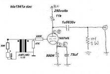
The impedance presented by the tranny primary is 47000 / (15x15) = 209 ohms. 100uF has 32 ohms reactance at 50 Hz. Go for 5 or 10 times that capacitance value.tone said:hi all,
Circlotron:a resonably large cap inseries with the transformer primary to block the DC.
>would 100uf ok? or is it too big.. tone
Post #18 is the way I would do it. Doesn't matter if the cap is in either end of the primary. What matters is that only the primary and cap are in series, as per the drawing in post #18.
Gapped transformer = leakage inductance = poor frequency response.Just wondering, could a gapped xformer be used here?
The forgoten Kirchhoff...
Are you sure?
As the kirchhoff law state that "for a series circuit the current is the same everywhere"
So it as clear to me that the capacitor in top...capacitor in botom doesn't matter...because the driving impedance more the capacitor impedance will be the same in any case...and is this impedance asn the load impedance that define the current!
Regards
With the cap in the bottom, some signal is capacity coupled directly across the transformer. The cap is isolated from the high frequencies by the inductance of the primary, so some inductance in the cap doesn't matter so much.
Are you sure?
As the kirchhoff law state that "for a series circuit the current is the same everywhere"
So it as clear to me that the capacitor in top...capacitor in botom doesn't matter...because the driving impedance more the capacitor impedance will be the same in any case...and is this impedance asn the load impedance that define the current!
Regards
Now consider that the capacitor has some inductance and resistance, and that the transformer has capacitance between primary and secondary:
With the cap in the top, the cap's inductance is in series with the transformer's capacitance between the top of the primary and secondary, thus is in series with some of the signal.
With the cap in the bottom, some signal is capacity coupled directly across the transformer. The cap is isolated from the high frequencies by the inductance of the primary, so some inductance in the cap doesn't matter so much.
Post #18 is the way I would do it. Doesn't matter if the cap is in either end of the primary. What matters is that only the primary and cap are in series, as per the drawing in post #18.
As the kirchhoff law state that "for a series circuit the current is the same everywhere"
Am I the only one that thinks this matter is contradictive ?
Jean-Paul,
Will you first consider whether the phasing of the transformer matters (assuming that signal polarity could be fixed elsewhere)?In considering, remember that there is parasitic cpacitance from primary to secondary along the full length of the windings.
If you can see this, then my other remarks make sense.
If you cannot, then I suggest that you try it on a transformer of suitably high inductance. I'm sure you'll see the effect!
Here's one where it mattered:
See http://www.diyaudio.com/forums/show...e=40&highlight=phase transformer&pagenumber=2 Post 60 with reference to this circuit: http://www.homepages.hetnet.nl/~rjonkers/amp.jpg
So with this information we can see that the transformer is not a "text book" case, but a real transformer with imperfections. It's those imperfections that make a difference.
Cheers,
I'm sure you're not!Am I the only one that thinks this matter is contradictive ?
Will you first consider whether the phasing of the transformer matters (assuming that signal polarity could be fixed elsewhere)?In considering, remember that there is parasitic cpacitance from primary to secondary along the full length of the windings.
If you can see this, then my other remarks make sense.
If you cannot, then I suggest that you try it on a transformer of suitably high inductance. I'm sure you'll see the effect!
Here's one where it mattered:
See http://www.diyaudio.com/forums/show...e=40&highlight=phase transformer&pagenumber=2 Post 60 with reference to this circuit: http://www.homepages.hetnet.nl/~rjonkers/amp.jpg
So with this information we can see that the transformer is not a "text book" case, but a real transformer with imperfections. It's those imperfections that make a difference.
Cheers,
Hi,
I should also add that it matters which end of windings is "hot".
Performance is always better if the hot end is the winding "outer" (for single bobbin construction).
If you want to invoke kirchhoff's law and others to explain circuit operation, you must consider ALL the elements.
Cheers,
I should also add that it matters which end of windings is "hot".
Performance is always better if the hot end is the winding "outer" (for single bobbin construction).
If you want to invoke kirchhoff's law and others to explain circuit operation, you must consider ALL the elements.
Cheers,
dac
hi all,
did couple of different mod:
1)mod on bottom primary with 100uf reversed. experincing distortion at upper frequency example vocal, is the cap too big in value or too low..or did i do something wrong..??
2)did circlotron mod..connect a 1000uf caps btw the resistor and the primary trasnformer winding, bass extention is back, great.
3)connect a 0.1uf caps btw resistor and primary transformer..eric clapton sound like chip-munck
question: would it be better to combine both mod together?
>should i add filter (inductor and caps) after the transformer secondary, according to thorsten circuit, he had inductor,caps, inductor in btw the secondary and tube grid resistor?
>i would say the sound is quite promising, beautiful midrange, now great bass extension , detail..hmmm..what should i ask more
>ohyah!..was thinking of adding a digital input transformer (pulse)..would a ratio 1:1 better, or a ratio 1:2 is better??
>thanks guy for the help..
>Best Regards,
>tone.
Tone,
I would use the largest cap you've got in the bottom end.
If you fit the resistor on the source side, the cap value need not be so big.
I don't understand where the 0.1uF comes in
If you want to try a pulse transformer 1:1 is best. Make sure the 75 ohm term resistor is on the secondary.......This may cause some debate
Cheers,
Zo.
Hi,
Well, it will all depend on the input impedance of the next stage, won't it?
50K or higher would fine...I'd still put in a higher value coupling cap at the output though.
John,
Do you mean a digital xformer as in a digital volume control?
Cheers,
Hi,
Just notice the change of anode resistor. Not so troubled now
Well, it will all depend on the input impedance of the next stage, won't it?
50K or higher would fine...I'd still put in a higher value coupling cap at the output though.
John,
Do you mean a digital xformer as in a digital volume control?
Cheers,
- Status
- This old topic is closed. If you want to reopen this topic, contact a moderator using the "Report Post" button.
- Home
- Amplifiers
- Tubes / Valves
- dac tube output stage..pls help.