would you feed back the voltage(collector) output to ccs transistor base or reference adj ?It might allow the current input to have lower impedance.
Yes sure, there are ways to lower the input impedance with some sort of feedback arrangement. But that was beyond my idea at the time.
Years later I did something similar with a tube, with the current inserted into the cathode, signal picked off at the anode. A cathode has much higher impedance than your average emitter, so I used feedback to the grid to lower the impedance. Worked fine but looked funny; a bunch of solid state including an opamp to put a stranglehold on a lonely tube and I concluded I wouldn't want to publicize such a travesty ;-)
Jan
I concluded I wouldn't want to publicize such a travesty ;-)
Jan
The is VERY funny Jan!
")
Most probably it would have been similar to the Audio research mcp-33 mc phono preamp, except that you didn't perhaps use a cascode there:Yes sure, there are ways to lower the input impedance with some sort of feedback arrangement. But that was beyond my idea at the time.
Years later I did something similar with a tube, with the current inserted into the cathode, signal picked off at the anode. A cathode has much higher impedance than your average emitter, so I used feedback to the grid to lower the impedance. Worked fine but looked funny; a bunch of solid state including an opamp to put a stranglehold on a lonely tube and I concluded I wouldn't want to publicize such a travesty ;-)
Jan
ARCDB - MCP-33
I was thinking more of a reversed White cathode Follower where i use the output as an input...
Ad844 won't have input impedance below 50 ohms even if we use the feedback , that is why they use ad844 paralled in open loop, but with a discrete circuit we have access to the ccs base or adj pin.
It's funny for me to go through tons of modern variations and schematics and in the end to find out that a classical discrete circuit with 5 transistors can do anything we need in the audio world just because we were told for too many times that ultra low thd matters, while tape or vinyl guys will laugh in your face with their 1% distortion figures...
Last edited:
Ad844 won't have input impedance below 50 ohms even if we use the feedback
Sure it does, it gets its open loop input impedance reduced by the feedback in the closed loop case. Assuming we're talking the -ve terminal here, right?
"It is important to understand that the low input impedance atSure it does, it gets its open loop input impedance reduced by the feedback in the closed loop case. Assuming we're talking the -ve terminal here, right?
the inverting input is locally generated and does not depend on
feedback. This is very different from the virtual ground of a
conventional operational amplifier used in the current summing
mode, which is essentially an open circuit until the loop settles.
In the AD844, transient current at the input does not cause
voltage spikes at the summing node while the amplifier is
settling. Furthermore, all of the transient current is delivered
to the slewing (TZ) node (Pin 5) via a short signal path (the
grounded base stages and the wideband current mirrors)."
I'm quoting the datasheet...I never considered to read it until 2 weeks ago and i was amazed after a talk with a friend of mine who is using ad844 Pedja circuit (open loop) to find that he was thinking that his circuit impedance is a few ohms just because it sounds very well for him...
I have 4x ad844 which i bought a month ago and now i simply know that i can't use them in closed loop with better results than the Pedja Rogic circuit.It seems that he read the datasheet, his followers didn't...
That might be a strong argument for why we "need" Jesus in our lives
Someone must do the dirty work for us.
Last edited:
In this case Pedja Rogic is wrong as he's using a high power buffer anyway and if you apply feedback to ad844 which is extremely fast, we should have the perfect i/v conversion...I launched a small question on the ad844 biggest topic, about what disqualifies the AD844 being used in closed loop as both its input and output impedance should drop significantly too and i was just told a classical religious text:This is just telling you that the input impedance of the inverting input is low before the application of feedback, unlike a VFB. Feedback will still effectively reduce the input impedance further. This is not unique to AD844, it's a feature of CFAs.
"There must be someone here who posted some measurements showing so"...but no real evidence of it.
In this case Pedja Rogic is wrong as he's using a high power buffer anyway and if you apply feedback to ad844 which is extremely fast, we should have the perfect i/v conversion...I launched a small question on the ad844 biggest topic, about what disqualifies the AD8884 in being used in closed loop as both its inpit and output impedance should drop significantly too and i was just told a classical religious text:
"There must be someone here who posted some measurements showing so"...but no real evidence of it.
I have no idea what Pedja claims or does in his design. It doesn't matter. The fact is that you can find the derivation of this on Page 9 of the linked PDF:
http://www.ti.com/lit/an/snoa376b/snoa376b.pdf
"A practical current feedback opamp has a finite inverting input impedance, less than 100Ω. Feedback reduces this further by dividing the initially low open-loop inverting input impedance by the loop transmission. The result is a better incremental ground at the inverting input to very high frequencies."
There are cults in the audio world that dislike feedback for various reasons. I suspect the decision to use the part open loop is just because you can.
Last edited:
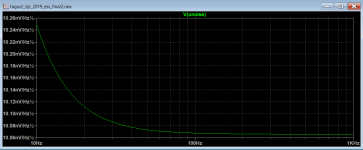
Keantoken is right, the input transistors are not very important for total noise, the ones that matter are the ones in the current sources and the emitter resistance of those bjt, there are some modern transistors that have rbb of less than 2 ohms (0.2 nV/√Hz), and those are perfect for the current sources
Noise for BC337/327 is less than 1nV/rt Hz.
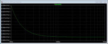
WRT CCS generated noise, use larger value resistors and a larger ref voltage. As such there will be lower current gain and hence less current generated noise at OP.
Clear as mud
T
That's true :Noise for BC337/327 is less than 1nV/rt Hz.
WRT CCS generated noise, use larger value resistors and a larger ref voltage. As such there will be lower current gain and hence less current generated noise at OP.
Clear as mud
T
https://www.diyaudio.com/forums/digital-source/336480-stage-town.html#post5756500
But I'm going to use 2sa1038 in my toys just because i can
Noise for BC337/327 is less than 1nV/rt Hz.
WRT CCS generated noise, use larger value resistors and a larger ref voltage. As such there will be lower current gain and hence less current generated noise at OP.
Clear as mud
T
Hi terry, yes you´re right of course, this is a project in evolution and in the almost final version the voltage ref for the ccs is almost 11 volts
Attachments
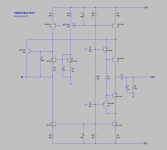
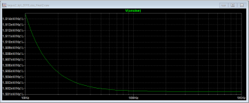
I decided to add the resistors (R8, R11) to lower the gain of the input stage and allow the use of a lower capacitor for the compensation, these resistors also decrease the voltage variations in the output due to temperature variations.
The circuit is stable even with a capacitive input.
With this resistors the input impedance is 0.2 Ohms from zero to 100Khz and increase to 0.5 Ohms at 1Mhz
The circuit is stable even with a capacitive input.
With this resistors the input impedance is 0.2 Ohms from zero to 100Khz and increase to 0.5 Ohms at 1Mhz
Looking at your circuit I had the idea to do this:
https://www.diyaudio.com/forums/dig...e-converter-error-correction.html#post5757013
Hi terry, yes you´re right of course, this is a project in evolution and in the almost final version the voltage ref for the ccs is almost 11 volts
Hello and thanks for your big effort, do the circuit work with a ES9018 Dac chip coupled for all 8 channels in parallel/ 16mA output?
Thanks
- Status
- This old topic is closed. If you want to reopen this topic, contact a moderator using the "Report Post" button.
- Home
- Source & Line
- Digital Source
- dac I/V convertion with very low distortion