Dirk, the spice models that you use in MJE15032c, MJE15033c are from Bob Cordell ?
If they are , is something wrong with the early voltage in those models, it gives better THD than in reality , try to replace with other transistors , and run the simulation again.
Using r10 and r11 with 100m gives good results in simulation but in reality will give bad temperature behavior.
If they are , is something wrong with the early voltage in those models, it gives better THD than in reality , try to replace with other transistors , and run the simulation again.
Using r10 and r11 with 100m gives good results in simulation but in reality will give bad temperature behavior.
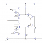
I was not happy with the solution of paralleling 4 board for the es9012 / 9018. I have thought in using a different input for this type of dac , it has less than 500mohms of input impedance, it is biasing at 60ma . what you guys think ?
Q1 and Q2 will be bd139/bd140.
meanwhile i am waiting for the components to arrive to try my test boards.
Q1 and Q2 will be bd139/bd140.
meanwhile i am waiting for the components to arrive to try my test boards.
Attachments
Try a CCS instead of the zeners.
Those are CCS's... <g>
They are constant current diodes (an fet + resistor in a tiny package).

Dirk, the spice models that you use in MJE15032c, MJE15033c are from Bob Cordell ?
If they are , is something wrong with the early voltage in those models, it gives better THD than in reality , try to replace with other transistors , and run the simulation again.
Using r10 and r11 with 100m gives good results in simulation but in reality will give bad temperature behavior.
Oh pish pash. You're acting like I'm actually going to build the thing... Nothing could be further from the truth.
I had this power diamond buffer lying around and I got an idea in the middle of the night, "what if I replace the BUF634 with this thing?". I just thought I'd share it for entertainment. I mean, is anyone really considering putting high current TO-220 transistors into an IV converter!??! I'm not...
You right Dirk. I need to relax.
Well, my original power diamond buffer had TO-3 output transistors!
Be the first in your country to put TO-3's in your IV converter!
hahaha
Hey Dirk,
I think Sergio is working up to TO-3, he's going for TO-126 (BD139/140) first ;-)
Good work Sergio!
This ess dac are a real challenge , maybe I will need to use some TO-3 in the end
Hey Dirk,
I think Sergio is working up to TO-3, he's going for TO-126 (BD139/140) first ;-)
Good work Sergio!
It's only a matter of time my friend, only time. Eventually, everyone goes for a TO-3. It's the biggest hammer in the tool box.
hi smms
I considered CFP but dismissed.
the CFP itself is 2 stage feedback amplifier, then it has slew rate limit, moreover asymmetrical rise and fall.
I think the charactaristics are not suitable for our application.
I will investigate that. In simulation it gives good results even with 50 ohms input impedance.
One thing is for sure . the bias of the input transistors have to be between 60ma and 100, for increase linearity, we have to use some to126 devices with heatsink or paralleling some pairs of BC327/337.
Using feedback with this type of dac are very tenting

Last edited:
To increase flexibility and compatibility with more dac chips, I have included a reference voltage input , for use with dacs that need a offset voltage at the input, like ess9018 , ess9012. The new input is the one named "SET".
Have you tried this I/V with the TDA1541, I imagine the SET is where one would inject the 2mA offset it requires?
No problem with 60-100mA! Plenty of good devices to use. Size TO220 is also possible. For ex the audio drivers
2SC4973+complementary
2SC5171+complementary (very linear, fast)
/S
2SC4973+complementary
2SC5171+complementary (very linear, fast)
/S
I will investigate that. In simulation it gives good results even with 50 ohms input impedance.
One thing is for sure . the bias of the input transistors have to be between 60ma and 100, for increase linearity, we have to use some to126 devices with heatsink or paralleling some pairs of BC327/337.
Using feedback with this type of dac are very tenting
modern CFA op amp do much better than descrete Q at their appropriate power, V levels
pwr pad CFA op amp like TPA6120 do single digit W, >200 mA, and have ppm audio distortion specs - and work up to 100 MHz - in closed loop
why would anyone today lust after big Q in DAC I/V?
pwr pad CFA op amp like TPA6120 do single digit W, >200 mA, and have ppm audio distortion specs - and work up to 100 MHz - in closed loop
why would anyone today lust after big Q in DAC I/V?
I was not happy with the solution of paralleling 4 board for the es9012 / 9018. I have thought in using a different input for this type of dac , it has less than 500mohms of input impedance, it is biasing at 60ma . what you guys think ?
Q1 and Q2 will be bd139/bd140.
meanwhile i am waiting for the components to arrive to try my test boards.
Now you are getting a little lazy, using CFP connected transistors to handle
the high current swing / low OP Z of Sabre.
You can get -super- low distortion fron Sabre using very simple open loop
I-V , even without the small + feedback loops, but you must think very
laterally
ZZ
hi smms
I considered CFP but dismissed.
the CFP itself is 2 stage feedback amplifier, then it has slew rate limit, moreover asymmetrical rise and fall.
I think the charactaristics are not suitable for our application.
WRT CFP, I agree.
In fact I consider the small + feedback loops a violation of the open loop theme
- but that point could be argued forever, life is too short
I will investigate that. In simulation it gives good results even with 50 ohms input impedance.
One thing is for sure . the bias of the input transistors have to be between 60ma and 100, for increase linearity, we have to use some to126 devices with heatsink or paralleling some pairs of BC327/337.
Using feedback with this type of dac are very tenting
Yes, oh yes, soon will come the day when you give up on those wimpy little transistors and embrace your true manhood with a pair of TO-3 monsters.
Yes, oh yes, soon will come the day when you give up on those wimpy little transistors and embrace your true manhood with a pair of TO-3 monsters.
And the bigger the bjt the slower / more non linear it is.
There is an art to picking the right device for a particular place in this
circuit and running it at the right current.
Z
- Status
- This old topic is closed. If you want to reopen this topic, contact a moderator using the "Report Post" button.
- Home
- Source & Line
- Digital Source
- dac I/V convertion with very low distortion