...any noise that the servo generate will be filtered by C2 and C3 (I have already test this, and work very well). So this I/V converter will not have output capacitor.
Sergio,
I very much like your use of a current mirror to simultaneously implement both the current source and servo. Killing two birds with one stone; as we like to say in the U.S.
 . Particularly beneficial is the embedded RC filter of the servo that not only filters the servo amplifier's intrinsic noise, but also any power supply noise coupled via the servo amplifier. In addition, it places an additional pole in the the overall servo transfer function which has a cutoff frequency more than four times lower than that of the active filter pole. Very nice.
Last edited:
I have more faith in the BJT version.. I have made phono-stages with Jfets, they always sound nice, but also wailed and cloudy compared to the Bjt's
Like your Servo- very much, the same way I designed one in for the paradise phonostage--there we use the OPA134.
I would make a jfet current source instead of the two resistors setting the current. and then insert the servo with two 100 kohm resistors on each side of the CCS.
I would then use the 6.2mA countercurrent to trim the offset to 0 before engaging the servo.
Then you know the servo is just dealing with thermal drift.
I agree if we can make a Jfet I/V with much less complexity, IMHO simplicity is the only reason to used a Jfet Non-NFB I/V with the rare except of DAC chips like the Ti PCM179x that have high output imp.
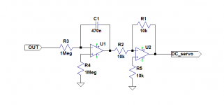
I use version 2. If you use version 1, I would change R4 into 1Meg for lowest possible DC offset from the OPamp itself.
OPamps:
OPA627B
OPA827 (SMD only)
OPA134
AD820
A servo should only take care of the last few mV of DC offset for temperature drift and component drift over time. The major DC offset fix should be a trim pot somewhere.
/S
OPamps:
OPA627B
OPA827 (SMD only)
OPA134
AD820
A servo should only take care of the last few mV of DC offset for temperature drift and component drift over time. The major DC offset fix should be a trim pot somewhere.
/S
The Dc servo will be one of this, the first is recommended by Bob Cordell and only use 1 capacitor. Can you guys recommend a jfet opamp with good dc precision for this, no need for low noise.
One kg of BC327:s - LOL!
Yes, they are costly (but not expensive). Think of them as tubes
I have also bough from Spencer. Never fakes from him.
When you design the ESS9018 stereo and mono mode version, if you can, try to get Zin of the IV converter < 1 Ohms up to 100+ kHz, please.
/S
Yes, they are costly (but not expensive). Think of them as tubes
I have also bough from Spencer. Never fakes from him.
When you design the ESS9018 stereo and mono mode version, if you can, try to get Zin of the IV converter < 1 Ohms up to 100+ kHz, please.
/S
As the pcm1794 has a high output impedance i thought about using the 2sk170/2sj74 pair in the input. I have bought 4 matched pairs from Spencer Cheung, they are not cheap, it cost the equivalent of 1 Kilo gram of BC327
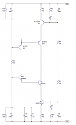
I have found an elegant soluction to connect the dc servo, instead of connecting the servo at the input as usual, the servo will be connected to the input of current sources, any noise that the servo generate will be filtered by C2 and C3 (I have already test this, and work very well). So this I/V converter will not have output capacitor.
In the schema is absent the ccs of 6,2ma for balance the pcm1794 dc_offset.
I will do also a version with BC327/337 transistors in the input. And i am working in a I/V for the ESS9018 .
Sergio,
Killing two birds with one stone; as we like to say in the U.S.
No birds were killed or injured during the making of this project. ...at least until now.
OPA827 has only 0.1mV.
OPA827 is very good for servo, the price is a bit higher.
staccatiss thanks for the list of opamps, and do not worry, the input for the I/V converter for the ESS9018 will be less than 1 ohm,
Just one question regarding the ess9018 . Why use all the 8 output in parallel? one can use only one output per channel and shunt the remaining 6. anyone know the reason?
Just one question regarding the ess9018 . Why use all the 8 output in parallel? one can use only one output per channel and shunt the remaining 6. anyone know the reason?
The current-mirror, mirrors the impedance you have in your current source, here it's 20 Kohms.. By inserting a Jfet CCS you up that many times. that was the reason for my suggestion.. then you could end with a CCS impedance of app 200k Ohms, or app 10 times better than what you have in your schematic.
Last edited:
MiiB, this is not really a current mirror, it depends the way you look at the circuit.
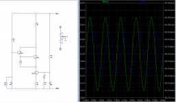
In this picture there is a simplified schema of the current source, as one can see i have change the 2 bipolar transistors by 2 diodes because they are connected as a diode and they only serves to temperature stabilization.
the voltage at the base of Q7 and Q9 are stabilized by the capacitors C2 and C3 ,normaly you see zeners or led in the place of resistor R8 or R18, but as long as vcc and vdd dont vary with temperature (use a lm317, 337 in power supply ) there is no need as C2 have much less impedance than any zenner or led.
this ccs is also cascoded so the output impedance is very high. Please trust me, this is a very quiet ccs , the noise floor of the I/V converter is realy very low. i will post pictures of that later on.
Attachments
You are absolutely right that one can use the 16 DACs inside the ESS9018 for 8 channels but using paralleled DACs gives better performance (THD and noise wise). Many commercial high end audio companies use DACs paralleled be it PCM1704, or PCM1794, or ESS9018 or the TDA-series.
Using the DAC in mono mode gives the advantage that each ESS9018 chip is separate for each channel. Also often used by high end audo companies.
< the input for the I/V converter for the ESS9018 will be less than 1 ohm,
Great!
/S
Using the DAC in mono mode gives the advantage that each ESS9018 chip is separate for each channel. Also often used by high end audo companies.
< the input for the I/V converter for the ESS9018 will be less than 1 ohm,
Great!
/S
staccatiss thanks for the list of opamps, and do not worry, the input for the I/V converter for the ESS9018 will be less than 1 ohm,
Just one question regarding the ess9018 . Why use all the 8 output in parallel? one can use only one output per channel and shunt the remaining 6. anyone know the reason?
to obtain insanely high SNR...despite nothing improve THD at fullscale.Why use all the 8 output in parallel?
Last edited:
The Dc servo will be one of this, the first is recommended by Bob Cordell and only use 1 capacitor. Can you guys recommend a jfet opamp with good dc precision for this, no need for low noise.
TL052 is a good jfet opamp.
tl052 is a possibility. But i will use for now OPA2134, of course others opamp can be use.
I have test the circuit with five OPA2134 , 2 of them give output of 200uV, 2 give less than 100uV and one give 800uV.
There are a lot of very high precision low voltage opamp out there, like for exemple the
max4238 it is a cmos opamp it cost less than 1 euro and has 0.1uV offset voltage , 10nV/Cº Drift , 1 pA input bias current. the maximum P.S. voltage is 5V.
A servo should only take care of the last few mV of DC offset for temperature drift and component drift over time. The major DC offset fix should be a trim pot somewhere.
/S
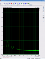
There is no need for a trimmer, the output D.C. voltage of the I/V converter is always the input offset voltage of the servo opamp, i have inbalance the input with 8ma on purpose and the D.C. output stay in the 100uV. i have also made a temperature test, and there was no variation at 50Cº.
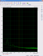
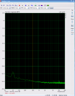
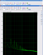
The servo that i test is this one, i use a 1Meg in R4 as staccatiss suggested but there is no difference, but i will leave it like that. the next image are the I/V converter noise floor with servo, the second image is without servo, the third is emu1212m alone. The last one is the power supply noise alone.
Attachments
- Status
- This old topic is closed. If you want to reopen this topic, contact a moderator using the "Report Post" button.
- Home
- Source & Line
- Digital Source
- dac I/V convertion with very low distortion